The RS241 have Mu of 17 so you need 3V input from your Linestage for full power and yes it will work with your interstage transformer. But the availibility of the tube is a problem. Its really rare in good condition. The 20b from EML is infact a reconstruction of the RS241 and its avalible.
A mu of 17 with a 300b/2a3/45 output is only practical into highly efficient speakers. Otherwise you're shifting the issue of gain back to whatever is supplying the amplifier. I went through a lot of the options last year and gave up. I tried an op-amp stage, a 1:2 step-up transformer, a preamp stage etc. In the end I found some indirectly heated driver tubes I was happy with, which is the conclusion many of us come to in the end with 2 stage amps with DHT outputs. I can use an input tube with a mu of 27 with a plate choke - just about. Mu of 30-40 is more realistic. Just one way to do it, but it gave me the best results when feeding the amp directly from a DAC.
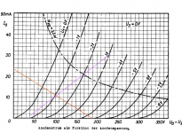
Ra of RS241 is 3100 Ohm.
With Tango NC20 it works fine but dont know how good the intactaudio IT is
A mu of 17 with a 300b/2a3/45 output is only practical into highly efficient speakers. Otherwise you're shifting the issue of gain back to whatever is supplying the amplifier. I went through a lot of the options last year and gave up. I tried an op-amp stage, a 1:2 step-up transformer, a preamp stage etc. In the end I found some indirectly heated driver tubes I was happy with, which is the conclusion many of us come to in the end with 2 stage amps with DHT outputs. I can use an input tube with a mu of 27 with a plate choke - just about. Mu of 30-40 is more realistic. Just one way to do it, but it gave me the best results when feeding the amp directly from a DAC.
Fully agree,I have a 45 with a VT25 driver and a Lundahl LL7903 input transformer 1:4, but you need a line stage with a very low Z-out to drive the transformer correctly.
I am now a big fan of Pentode drivers and especially the C3m/C3o. But I am also waiting for the redesign of the Shunt Cascode by Ro Coleman 🙂
I used to own the Tango NC20. I replaced it with the IntactAudio Interstage Transformer. I found the IntactAudio to be more transparent and have more realistic tonality. Also, the bottom end was fuller and more extended with the IntactAudio.
I use the EMIA Elmaformer as my passive line stage. It has 150H of inductance. Excellent passive attenuator.
So, from what I am gathering, we need a mu of 30+, preferably 40+, correct?
The EML 30A has a mu=32, 400V, Ra=19K, Rp=6.2K. wondering if this might be a decent alternative as a driver in my amp?
Cagomat - have you compared the C3g vs. C3m/C3o?
euro21 - you mentions the RS241 Ra = 3100. Please share your thoughts on why this is a good or poor match with the 5K IT.
Rule of thumb: the load must be twice, rather three-five times the size of Ra.
So if I would try RS241, the requested minimum load would be 7-10k.
According to my experiences the "average" interstage (with proper inductance) requiring much smaller driver output impedance, than in theory.
For example I have 42H and 130H Slagle 1:1 ITs.
The first one has 5k2 impedance at 20Hz, but sounding a little weak with 2-3k output impedance tubes, but good with -about- 1k tubes.
The later is perfect even with 10/801 at 20Hz.
I use only low rp driver with IT like D3a. Best is plate chok direct coupled or LC. But the best driver I ever used is C3m/C3o as pentode. On par is 10Y/VT25 with input transformer. ( I used UX210 from 1924)
I used to own the Tango NC20. I replaced it with the IntactAudio Interstage Transformer. I found the IntactAudio to be more transparent and have more realistic tonality. Also, the bottom end was fuller and more extended with the IntactAudio.
I use the EMIA Elmaformer as my passive line stage. It has 150H of inductance. Excellent passive attenuator.
So, from what I am gathering, we need a mu of 30+, preferably 40+, correct?
The EML 30A has a mu=32, 400V, Ra=19K, Rp=6.2K. wondering if this might be a decent alternative as a driver in my amp?
Cagomat - have you compared the C3g vs. C3m/C3o?
euro21 - you mentions the RS241 Ra = 3100. Please share your thoughts on why this is a good or poor match with the 5K IT.
The EML 30b is not usable with IT in my option. Maybe gyrator or CCS but have no experience with such loads
My plate chokes are NP Acoustics amorphous - I have a large one at 180H, 40mA and a couple of small ones at 136H, 15mA. These allow for driver tubes with around 12K anode impedance. Lundahl do the LL1668/15mA at 167H for instance. A ratio of 10:1 is good for an anode choke. It will work with less, and I've used a Hammond 157G at 30H. But it's good to have more Henries.
I used to own the Tango NC20. I replaced it with the IntactAudio Interstage Transformer. I found the IntactAudio to be more transparent and have more realistic tonality. Also, the bottom end was fuller and more extended with the IntactAudio.
I use the EMIA Elmaformer as my passive line stage. It has 150H of inductance. Excellent passive attenuator.
So, from what I am gathering, we need a mu of 30+, preferably 40+, correct?
The EML 30A has a mu=32, 400V, Ra=19K, Rp=6.2K. wondering if this might be a decent alternative as a driver in my amp?
Cagomat - have you compared the C3g vs. C3m/C3o?
euro21 - you mentions the RS241 Ra = 3100. Please share your thoughts on why this is a good or poor match with the 5K IT.
A optimum match would be a driver with a rp between 1k and 1k5. for what current is your IT gapped?
The problem is when the Ck of the C3g is way too low, anode resistance rise up. Normally the IT is perfect for this tube.
euro21,
1) good catch. the C3g (not D3a) cathode R = 100, not 180 as listed. Thanks.
2) what do you mean "IT hasn't correct secondary termination"? How should it be terminated?
Updated schematic below
Thanks!
I would use a different operation point. 200V @ 10mA
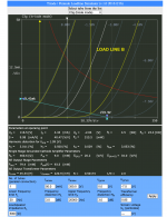
Need some help on C3g load lines.
These are the actual measurements:
Ua = Voltage at top of plate: 179 Vdc
Ug = Bias voltage: 2.3 Vdc
Rk = Cathode resistor: 100 ohms
Ri = Plate Internal resistance = 2.3K ohms
So, a few questions:
1. Should the load line intersect the x-axis at 179V or 176.7V (179-2.3)? I know this is minor, but just need to know in theory which is correct.
2. should the load line intersect the y-axis at 23mA (2.3/100*1000)?
The attachment assumes 179V at 23mA. This is the RED load line. Then, the magenta line is the Cathode Load Line.
So, where would I try to select an operating point? At the intersection of load line and Cathode load line? Or some other point on the Cathode Load Line? Other? I like a fuller sound on my chamber string music.
Thoughts?
Attachments
banpuku,
Your graph:
Start with the plate current and plate voltage you want (for example, 165V and 20mA).
Mark that exact point on the graph.
Why did I pick that voltage and current? . . . because you do not have to operate the tube exactly at its maximum plate dissipation. Let the tube breath a little, and relax slightly.
The plate voltage on the graph is defined as the Plate to Cathode voltage.
The plate voltage markings on the graph do Not include the grid bias voltage from the self bias resistor.
Suppose the above plate current and plate voltage point is directly on one of the grid bias lines, It is: -2V. Now you know what bias voltage you need, in order to set the self bias resistor. 2V/20mA = 100 Ohms
Suppose you picked a plate voltage and plate current point which is evenly between two adjacent grid bias lines.
Then the grid bias is 1/2 way from one grid line to the other grid line.
Etc.
Now, draw your load line from the quiescent point, to where the plate voltage becomes Zero. The quiescent plate voltage/load impedance = 20mA +20mA (40mA). Now, extend that line to the right where the plate current goes to Zero.
Now you need to mark the point on that load line where bias = 0 Volts, and mark the point on that load line where the bias is 2X the quiescent bias (so for the above case, the grid bias from 0 Volts, to -2V, to -4V). That is the range of your signal voltage from the driver, if you are not going to draw grid current.
Of course, if you use RC coupling for example, the signal voltage at the grid goes from +2 Volts, to 0 Volts, to -2V respectively.
You have to decide if you are going to bypass the 100 Ohm self bias resistor, or not going to bypass it.
If you do not bypass the 100 Ohm self bias resistor, the final plate resistance will be the bypassed plate resistance rp (+ u x 100 Ohms), a much higher plate resistance. u = 50
2,300 + (50 x 100) = 2,300 + 5,000 Ohms = 7,300 Ohms.
The un-bypassed stage will not drive a 5k plate load very well.
The gain will go down, and the maximum range of plate signal voltage before clipping will go down.
And as Cagomat said, you may choose to use a little more plate voltage and a little less plate current.
However, if you go to far that way, the tube will be operating in the very curved portions of the grid lines, and that = high 2nd harmonic distortion, and = high plate resistance, rp.
Talke a look at 160V plate, 14mA, and -2.4V self bias. The grid to cathode will swing from 0V to -5V, and there should be enogh plate voltage to drive the 45B +/-62V.
I hope that helps.
Last edited:
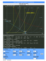
6A3sUMMER, Thank you! Helpful. I took the liberty of attaching 2 different load lines.
Load Line A: Ug=2.0, 179V, 22.2mA, 6.37% distortion at 2V input
Load Line b: Ug=2.0, 220V, 9.4mA, 3.01% distortion at 2V input.
My input is 2V
So, the question is: which load line should I go with? both have a p-p of 4V.
Load Line A: Ug=2.0, 179V, 22.2mA, 6.37% distortion at 2V input
Load Line b: Ug=2.0, 220V, 9.4mA, 3.01% distortion at 2V input.
My input is 2V
So, the question is: which load line should I go with? both have a p-p of 4V.
Attachments
Last edited by a moderator:
To draw a loadline, first mark a point at the chosen idling point, DC voltage and idling current. Then, draw a line through that point having the slope of your effective load.
For example, a 10K Ohm load has a slope of 10 Volts per milliAmp. If your chosen idling point is 176.7 VDC and 23mA, make a point there. Then mark the y-axis intersection at 23mA plus 176.7 Volts / 10K Ohms = 40.6mA. Next mark the x-axis at 176.7 Volts plus 23mA x 10K Ohms = 406.7 Volts. Draw a line through these three points.
That's how to do it with an inductor as the plate current source. For resistive loading, it's easier: start again by marking the idling point. Mark the x-axis at the B+ supply voltage; draw a line through these two points. The slope of this line is your load resistor for DC.
All good fortune,
Chris
Last edited:
I suppose I need to add that your unterminated interstage transformer is close to an open circuit through the large middle frequency range of its operation. Your working loadline will be essentially a horizontal line except at frequency extremes.
The important bit is that the loadline must pass through the valve's idling point. Always. And then work outwards from there.
All good fortune,
Chris
The important bit is that the loadline must pass through the valve's idling point. Always. And then work outwards from there.
All good fortune,
Chris
As Chris wrote earlier, and I also warns in #15
"Your IT hasn't correct secondary terminating. The transformed impedance at #D3a anode is indefinite, not 5k. "
must correctly load the IT.
Try paralleling 10k..22k resistor with IT secondary. Your reflected load to C3g anode will be - approximately - this value.
The resistor value is function of HF behaviour of IT. At few ten kHz every IT has a smaller or larger bump, this resistor value decrease (damp) it.
- Home
- Amplifiers
- Tubes / Valves
- Next steps: grid and supply chokes for C3g drives 45B