Hello everyone, Merry Christmas and many many thanks to Mr. Pass and all the nice guys on these forums who helped me build my first diy amp! The F2 is done and worked from the start. The sound is pretty good, I was expecting something even better to be honest but my setup is still suboptimal to say the least, with a mere 50k pot between the CDP and the F2 (DCB1 soon to be added). I'll post pictures later this afternoon.
However, there is a problem. When nothing is connected to the inputs, the amp is very quiet, there's only very little hum on the R channel, barely noticeable in sensitive headphones, probably from the trafo. When I connect anything, be it the CD player, a casette deck, an mp3 player or even solely the pot (at which the 2 signal grounds are connected), I get some noise like a buzz, louder on the left channel. This happens even if the CD player is turned off and disconnected from the mains. The only exception is a DVD player (with unearthed plug) which is being accepted by the F2 without any buzz until I turn the DVD player on - then I get buzz too. Inexperienced as I am, I'm tempted to believe it's a grounding problem, loop, whatever, but I couldn't solve it by myself, so please help!
There is a particularity of my F2 clone that I should mention. There is a kind of switch that allows me to choose an output with or without the 3 resistors of 47R in parallel to the speakers. Speakers are actually the AKG K1000 "earspeakers" and I have also installed a regular headphone jack (actually this is the switcher, but I won't go into details) that allows me to use my AKG K501 headphones as well but only with the resistors in parallel.
Below is a list of details and observations that could be relevant for you but I don't know how to interpret them:
1. At first the L and R grounds were connected together at the headphone jack and the noise was much louder, I could measure 6 mV AC on L and 4 mV AC on R channel without the resistors (with the resistors the noise is obviously reduced and below the 1mV AC measurement limit on my DMM). I cut one of the 2 ground wires at this jack and the noise is significantly smaller, to the point that I can barely hear it to the R (but to the L it is still annoying).
2. The other channel ground going to the hp jack touches the chassis, but lifting it did not matter.
3. The buzz is reduced if the parallel 47R resistors are connected.
4. If I connect (with or without CDP -->) potentiometer --> F2 inputs I get the least noise with the pot at medium position
5. If I connect the pot in reverse position, then the closer it is to 0, the lower the noise.
6. CDP and F2 are earthed, nothing else in the same power outlet. Before earthing the F2 chassis, it had a serious AC potential above earth, tens of volts (I even measured 136VAC once, this morning it was 58VAC) but probably very low amperage as I couldn't feel anything when touching it.
7. Connecting R channel input results in buzz on the R channel only; connecting L channel input results in buzz on the L channel and might also inflict some buzz on the R channel, but I'm not sure, it is very difficult for me to hear it right now (noisy traffic hour).
8. Some measurements I made yesterday inside the working amp:
- power voltage: 239VAC (could be between 234 and 241 other times)
- trafo out: 19.6VAC both channels
- bridges out: 23.5 - 23.6 VDC L / 23.6 VDC R
- psu out: 22.9 VDC L / 23.0 VDC R
- bias: 11.60 VCD L / 11.63 VDC R (it was decreasing slowly ~ 30-40mV / each channel as the amp was warming up, now was stable)
- temperature: 24C room, 45-46C transistors' plastic case, no top cover
What should I try next to get rid of the buzz? Thank you for any suggestions you may have!
Last edited:
Why did you remove the 47R resistors? To match the headphones' impedance?
How do you ground the different sections of the circuit?
Are the in-/outputs' grounds isolated from the chassis?
How is your transformer mounted?
What PSU are you using? How is it grounded/earthed?
Schematics and pictures would really help.
How do you ground the different sections of the circuit?
Are the in-/outputs' grounds isolated from the chassis?
How is your transformer mounted?
What PSU are you using? How is it grounded/earthed?
Schematics and pictures would really help.
Why did you remove the 47R resistors? To match the headphones' impedance?
How do you ground the different sections of the circuit?
Are the in-/outputs' grounds isolated from the chassis?
How is your transformer mounted?
What PSU are you using? How is it grounded/earthed?
Schematics and pictures would really help.
Pictures here. I've worked so hard building the amp, chassis & sinks that I didn't care much for the cosmetics at the moment, please ignore that🙂.
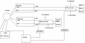
Grounding is like in the picture attached, with the following differences: there is also a thermistor in series with one of the trafo primaries; one of the output grounds touches the chassis at the regular headphone jack (I have tried removing the jack so that it doesn't touch the chassis anymore and there was no difference); also, L channel ground goes to the anodes of both leds, but I have tried lifting ground on both leds with no effect on the buzz. Before I had both output grounds meet at the jack and the buzz was much stronger. Earth and the 2 psu grounds (through thermistors) meet at the same point on the bottom of the chassis as you can see in the pictures.
So output grounds are connected through thermistors to the chassis, but only there - grounds are not connected between them or to the chassis at the input side of the amp.
PSU: the tiny pcb at the back of the chassis has fuse on one rail, thermistor on the other and the 0.0033uF cap between rails. Then the wires go to the front to the trafo primaries. The trafo is mounted with the included rubber washers and bolt to the bottom of the chassis; the secondaries go to the bridges, which are also directly mounted on the bottom to provide them some sinking. From each bridge output (with 2.2k resistors across) I got positive voltage and ground to the PSU, which is build as in the F2 schematic - actually, mostly everything is like in the F2 schematic, only difference being the physical placement of some parts such as the power input thermistor.
Regarding the 47R resistors, I wanted to be able to choose between the sound with and without them. I was expecting more bass without them, but to my surprise (perhaps because of the 120 ohms of the headphones) there is more and better bass with them. The connection is made like this: from the outputs (without resistors) the wires go to the 4 pins XLR on the front for the K1000 (grounds separated), then both channels and one ground go to the regular headphone jack. On the other hand, for each side, from the three 47R resistors - from the opposite side to the ground - goes a wire to the regular headphone jack that connects to the corresponding signal output every time a jack is inserted and disconnects when there is no jack. This way I always have the resistors connected when using the K501 and it's my choice to insert or not a jack adapter such as the one in one of the pictures when using the K1000.
Attachments
You are of course aware that the (+) outputs are ground,
and what you would ordinarily think of as (-) output
terminals are live.
😎
and what you would ordinarily think of as (-) output
terminals are live.
😎
Yes, I am, - output is coming from the 0 side of the output electrolytic cap, while + output is not actually + but, well, ground. Mr. Pass, why did you ask me this, do you have any clue what could be wrong with my amp?
If you tie the two black output terminals together into a
headphone, then the outputs will argue with each other.
😎
headphone, then the outputs will argue with each other.
😎
I know, but right now they are not tied together, the K1000 have separate grounds for each channel and the regular headphones are using only one of the grounds. I had the grounds connected together and the noise was much louder, but it still persists even after I have removed one of the grounds from the regular headphones jack.
Just to make it as clear as possible, the noise is present both in the K1000 (separate grounds) and in the regular headphones no matter if I connect only one of them or both.
Thank you for trying to help, please keep on posting, I really, badly need your assistance here!
Just to make it as clear as possible, the noise is present both in the K1000 (separate grounds) and in the regular headphones no matter if I connect only one of them or both.
Thank you for trying to help, please keep on posting, I really, badly need your assistance here!
Not that it's smart, but can you lift earth ground with a cheater plug, it might tell us if a noisy ground is part of the problem.
Of course, I wonder if you hook the thing to an ordinary small speaker, you can hear the buzz from 1 foot away. If you can't I suspect that it's a matter of moving cables around in my experience.
My F4 headamp has a tiny buzz to it, only heard on headphones, but once music is playing you don't notice. If I use it at work, which is noisy, I dont notice it at all. I know the reason for the buzz, the input wires (even shielded) are picking it up.
Noise remains the same if I lift the earth ground.
Cables alone do not give me any noise at all, the buzz comes up only if I connect the cables to something - anything except for the turned off DVD player. I have connected the F2 input wires to the 50k pot I mentioned above and I have played with it a bit moving it into all directions. No difference at all, to the ear or to the oscilloscope.
Shorting the inputs results in noise, but it's symmetrical and sound different to the evil buzz.
On the right channel it's quiet enough that I can't hear it at all in a noisy environment, but I can hear it on the left and if it's really quiet, late at night for example, it's really disturbing for me. All this in headphones, I don't have normal speakers but only active monitors.
This nearly has to be grounding I think. Somehow theres a ground loop when you connect another piece of equipment.....
Fran
Fran
I am not familiar with the F2, so you need to bear that in mind, but if it was me, I would have brought all the grounds together at one point and then connected that to chassis via the CL60. In other words a star ground.....
That might be easier to try first rather than changing the PS.
Fran
That might be easier to try first rather than changing the PS.
Fran
I believe the ONLY common ground on a F2 is shared at the backend of the two CL60s that connect to ground and to the chassis.
This is what I do on my F3, and it does not have this issue.
This is what I do on my F3, and it does not have this issue.
This would require access to the bottom of the PCBs that in turn would mean desoldering the FETs, inputs and outputs, lifting all the circuitry from the case, etc. etc. Much easier would be disconnecting the right channel completely from the power supply and perhaps also disconnecting the right channel psu ground from the chassis, and if nobody will suggest anything else I will do that too, but I bet it won't help.
There must be a logical explanation why connecting any channel's input to a pot - and nothing else - results in this buzz, but I have no idea what it could be.😕 Also why it's only the DVD player that doesn't give the buzz when connected to the F2 unless I turn it on (the DVD player).
I'm aware this is an inappropriate moment for this, so "Happy New Year!" to all of you - but please remember me and this thread next year...🙂
Haven't seen Tea-Bag's answer. Yes, he is true, take a look at the drawing attached to my second post.
Some new findings, maybe some will tell you something.
1. When connecting the left input to the pot and nothing else, I get a lower intensity buzz (on the left side) as compared to connecting both L and R inputs to the pot. However, connecting solely the right channel doesn't give buzz to the left on its own.
2. If I power it "correctly", with hot rail being the one with the fuse and neutral being the one with the thermistor, and unearthed, I get ~124 VAC between chassis and ground; connecting it the other way around gives ~86 VAC chassis to ground. In both cases current is below my measuring limit of 0.1mA (except for the first seconds from powering up when I measured ~0.4-0.5mA that decreased rapidly to <0.1mA).
Running the F2 over one section of PS draws more current through them. It may affect fidelity, and the resistors in PS will get warmer. There is enough capacity there to pull down 4 amps total.
I dont understand your reading of chassis to ground. That doesn't sound right, but I only work with 120v. I would consider being unsafe and pulling the connections to the chassis off. In these matters, best to work with a variac, and what we have here as a GFRI outlet.
A ground loop can be anything where the ground forms a circle in the system. Check the board you made for signal path wiring loops. Make sure RCA's are not hitting chassis ground and signal ground. Sorry if I am being redundant. Tired.
- Status
- Not open for further replies.
- Home
- Amplifiers
- Pass Labs
- Newborn F2 refuses mating, what's going on?