My son and I just built our first amp project but we ran into issues after powering it up. I used a TDA1517 salvaged from an old audio/video capture card and a DSL modem housing. The rest of the parts are new from Ratshack. We can hear music and a thumping sound out of the left channel. The music is quiet and the thump occurs about once a second. The right channel is dead. We are powering it from a 12VDC 1000MA wall wart. I was using a Sony Discman as a source for testing. I will say up front that I did not give enough thought to my ground implementation and plan to redo it next weekend. The volume control and power switch worked as they should.
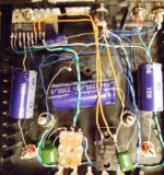
Left and right are reversed in the image.
This thread contains the wiring diagram I followed http://www.diyaudio.com/forums/showthread.php?s=&threadid=90487 which I confirmed is accurate per the original spec sheet from the manufacturer.
Any ideas? Thanks.
Left and right are reversed in the image.
This thread contains the wiring diagram I followed http://www.diyaudio.com/forums/showthread.php?s=&threadid=90487 which I confirmed is accurate per the original spec sheet from the manufacturer.
Any ideas? Thanks.
Attachments
I see many people have looked but no replies yet. Can anyone comment as to why no suggestions? Is the picture no good or is the whole thing that bad looking that there is no good starting point for helping?
I can upload a bigger picture this weekend if that might help.
I can upload a bigger picture this weekend if that might help.
hmmm... I suggest better used proto board@simple board for PCB because its looks hard to give suggestion with this situation, maybe peoples dont know which and where... to comments... 🙂
Try soldering some bypass caps *right on* the chips pins for +V and gnd.
Maybe something like a 0.01uf,and a 22uf in parallel.
It's important that they are very near the chip pins.
Maybe something like a 0.01uf,and a 22uf in parallel.
It's important that they are very near the chip pins.
DigitalJunkie's suggestion to solder the power supply bypass caps much closer to the power supply pins is a very good one. Your schematic specifies 100 uF and 0.1 uF from Vp to Gnd. Your photo is not quite large-enough for me to see if the 0.1 uF cap is present or not. In any case, while it is more important for the smaller cap to be closer to the pin, ideally the bodies of both caps would be as close as possible to the chip's power supply pin. (Also, you might want to experiment with connecting the ground end of the caps directly to the Pgnd pin (5).)
Wait. Are you SURE that the photo is left/right reversed?? If it's not (and it looks like it's not), then I don't see either the 100uF OR the 0.1 uF (100 nF) that should go from pin 7 to gnd! That might be your main problem. Solder them directly to the pin, with leads as short as possible, at least for the ones that connect to the pin.
Soldering: When soldering, you should try to use long-nosed pliers as a heatsink, between the device and the solder point. You can use a rubber band on the pliers' handle, for 'hands-free operation'.
I think that your layout and construction technique could be a significant problem. Lead-lengths and wire-lengths should usually be as short as possible, for example. And the enclosed loop areas of to/from pairs' current paths should be minimized. You can tightly twist together any paired wires, to minimize certain loops' areas. Others might depend on your layout being good.
A piece of perfboard, or whatever it's called, should give you a way to mount the components better, enabling you to design a more-compact layout (probably using radial-lead capacitors instead of the axial-lead type). Actually, any piece of thin, stiff, non-conductive material, and a drill, could also be used.
But suggesting a whole different layout doesn't necessarily address the problem you are having right now. Do you have a multimeter? If so, you can do some basic 'sanity-check' types of measurements. I'd start with making sure that the DC voltage between the chipamp's power pin and ground is what you think it should be. You could also measure the AC component, there. I would also disconnect the source and put a short across each input and then measure the DC voltage across each speaker, which should only be a small fraction of a volt.
Does the chip get hot? I cannot quite see how it is mounted. Typically, you would want the entire rear surface of the IC to be mounted against a heatsink. Usually, you would want to make sure that the heatsink is not in electrical contact with anything else.
Here is a much better picture. http://picasaweb.google.com/oatmealorama/TDA1517_AMP/photo#5177991070949438946
Thanks for the feedback at this point to everyone trying to help. My first priority is to try to get it working before making any major changes (like bread boarding it or changing the values of any caps) though I suspect that completely redoing it per suggestions might make my life easier.
I've never tried anything electronic without instructions or in kit form so unfortunately have no idea what readings should be at various points when probing with my multimeter for "sanity checks". How would I determine what readings should be at each point?
It was suggested by a friend that the chip might have been damaged by my soldering so I will replace the chip this weekend. If I can find a socket at ratshack I will solder that rather than the chip.
Again thanks for the assistance.
Yes the chip and the heat sink get hot. It stabilizes just under 180 deg F. The flat tab on the top of the chip is flat on the heat sink. Should I use a bigger heat sink?
Hi DJ, you just mount the TDA1517 chip on the top heat sink like that is not recommended, mout it on the flat heatsink not only top of the TDA ics but all the flat ics surface. I did build amp TDA7294 before, what i know is we must use correct heatsink to reduce ics become heat faster and blown ics in few mins, this is important thing to get correct heatsink for each power ics. Make it simple but be carefull with the heatsink thing that will waste your money 😀
Sorry for my bad language,i hope you can understand. I`m just new in here and try with little help, but i hope more experts peoples will help you out with professional suggestion. 😀
Sorry for my bad language,i hope you can understand. I`m just new in here and try with little help, but i hope more experts peoples will help you out with professional suggestion. 😀
Good point. Heat rises. I'll mount the chip on the bottom of the heat sink and see if that lowers the temp. Is that what you are suggesting or do you mean for me to have the actual black part of the IC in contact with the heat sink? I looked on the spec sheet and see that 180F is near its operating limit so the temp needs to come down a little at least.
dj_oatmeal said:Good point. Heat rises. I'll mount the chip on the bottom of the heat sink and see if that lowers the temp. Is that what you are suggesting or do you mean for me to have the actual black part of the IC in contact with the heat sink? I looked on the spec sheet and see that 180F is near its operating limit so the temp needs to come down a little at least.
Hi DJ, if your heatsink doesnt connect to ground (0V) and yes you can mount the ics directly, but if your heatsink connect to amp case which having ground connection you need to use silicon plastic to prevent electrical shock, i suggest for first powerup or testing your amp better use min voltage like 8volt, in normal operation when the amp in on mode and idle, tda ics should not become hot faster, i suggest before you connect to audio source, just test in idle mode lets see the ics become hot or not, if you have multimeter, you can check whether output having high dc current or not, if it doesnt have then power off, connect the output to the speaker and connect the input to the source, see its working or not.
DigitalJunkie said:Try soldering some bypass caps *right on* the chips pins for +V and gnd.
Maybe something like a 0.01uf,and a 22uf in parallel.
It's important that they are very near the chip pins.
Hi DJ,like DigitalJunkie said, this is also important to have dc decoupling, do you have it on your design? you need to use 100nf(0.1mfd) polyester film or 104J ceramic@mylar capacitor. 😀
Regards.
I have 100uF between pin 3 and GND. 2200uF and 104K on Vp. Pins 2 and 5 go straight to GND without any caps. Should I add a cap to these pins? If so I have 220uF available would that work or is that too much?
The heatsink is not grounded.
The heatsink is not grounded.
dj_oatmeal said:I have 100uF between pin 3 and GND. 2200uF and 104K on Vp. Pins 2 and 5 go straight to GND without any caps. Should I add a cap to these pins? If so I have 220uF available would that work or is that too much?
The heatsink is not grounded.
it seems like you`re following the right philips schematic, vp pin7 connect to +vdc power source and make switch for pin8 to connect to vp and must have 2200uf and 104 or 104 100nf parallel to GND, no need to add any caps to pin 5,2. as i can see you add volume (ROTARY POTENTIOMETER) for the input, try remove this one and connect directly from you sony discman, sometimes wrong wiring on volume control can cause no audio signal.
dj_oatmeal said:I have 100uF between pin 3 and GND. 2200uF and 104K on Vp. Pins 2 and 5 go straight to GND without any caps. Should I add a cap to these pins? If so I have 220uF available would that work or is that too much?
The heatsink is not grounded.
norazmi said:
it seems like you`re following the right philips schematic, vp pin7 connect to +vdc power source and make switch for pin8 to connect to vp and must have 2200uf and 104 or 104 100nf parallel to GND, no need to add any caps to pin 5,2. as i can see you add volume (ROTARY POTENTIOMETER) for the input, try remove this one and connect directly from you sony discman, sometimes wrong wiring on volume control can cause no audio signal.
I think you are both looking at the correct schematic.
The problem (with the caps) seems to be that they are not properly located.
The 0.1 uF (i.e. 100 nF/104) and 2200uF caps' bodies need to be as close as possible to pin 7, with the shortest-possible connections to that pin. If a compromise must be made, then the 0.1 uF caps should be closest to the pin.
I would also add a 0.1uF cap from pin 8 to power ground, similarly.
Any other capacitors that connect to the chip's pins should be located similarly, i.e. right AT the pins.
Any and all 'to/from' wire pairs should be tightly twisted together, e.g. input/input-shield 'gnd', power/gnd, switch and pot to/from, speaker hot/gnd, etc.
Wires with low-level signals should be routed away from high-current wires and components.
All wires and component leads should be as short as possible.
I would also try norazmi's suggestion and at least temporarily try it without the pot, removing the pot's wires at their far ends (i.e. don't leave them dangling from the chip etc, during any temporary test).
First, though, you "must" properly-heatsink the chipamp. Yes, its ENTIRE REAR SURFACE must be tightly-clamped to the large flat surface on the rear of the heatsink!
You should definitely use a thin layer of thermal heatsink compound "goo", between the chip and the heatsink (but can 'probably' get away with not using it, for testing, if none is on hand yet).
Since you probably don't have any chip-to-heatsink insulators on hand, make sure that the heatsink is not connected to anything else that is metal.
Maybe none of this directly explains or solves your problem. But the chip could have already been destroyed by either soldering without heatsinking between soldering iron and chip body, OR, it could have 'oscillated itself to death', because of concerns like those partially-addressed above.
High-frequency oscillation can quickly overheat and destroy a chip. Incorrect capacitor placement, and 'loose' layout problems, among other things, can cause HF oscillation.
It would probably also be very wise to add simple lowpass RF filters to the inputs. For that, you can put two resistors in series with each input, close to each pin (pins 1 and 9), with a small capacitor to ground from between each pair of resistors. Something around 470 Ohms for the four resistors, and 3300 pF polystyrene (probably best) or polypropylene or polyester or silver mica, or a C0G or NPO ceramic, for the caps, should work fine. You can scale the component values, as long as the R times C stays in the same ballpark (unless you want to raise or lower the filters' -3dB 'cutoff' frequency. A lower RxC raises it, and vice versa. f(-3dB) = 1/2/Pi/R/C in 'calculator format'.).
Its alive!!!
Thanks for all of the help with this so far. I redid it as simply as it could be done(for me) with no switch, no pot, and everything as short as possible all per the spec sheet. It sounds very nice even (dare I say it)comparing it to my tube amp. The layout is very ugly looking and I will need to redo it again to add back the conrols and get it to fit into some sort of housing. I'll upload a pic this weekend.
Thanks for all of the help with this so far. I redid it as simply as it could be done(for me) with no switch, no pot, and everything as short as possible all per the spec sheet. It sounds very nice even (dare I say it)comparing it to my tube amp. The layout is very ugly looking and I will need to redo it again to add back the conrols and get it to fit into some sort of housing. I'll upload a pic this weekend.
A little more info and a pic as promised.
The heatsink stays completely cold and the chip is just barely warm to the touch.
With nothing playing the speakers are silent even holding my head near them.
Need to work out a better layout and add back the switch and pot.
Again thanks for the help.
http://picasaweb.google.com/oatmealorama/TDA1517_AMP/photo#5180590043011459234
New Housing- Can I add tubes?
I made a new wooden housing for the amp and have enjoyed it for several months now but my wife thinks the sound is a little harsh in the high frequencys.
Can I add a tube (12au7 or 12ax7 since I have several of each) on the output side of the amp to smooth the sound out? I've been doing a lot of reading but so far have mostly found tubes on the input side of a hybrid amp setup. Nothing that gives me more than a hint of how to go about it on the output side. Thanks.
Pictures of the amp. Current form is in the wooden housing.
http://picasaweb.google.com/oatmealorama/TDA1517_AMP#
Have you tried different output capacitors.
The idea of throwing a tube to the mix sounds too complicated.Specially to the output,only to smoothen the sound
That nice wooden housing deserves better chip....
The idea of throwing a tube to the mix sounds too complicated.Specially to the output,only to smoothen the sound
That nice wooden housing deserves better chip....
I agree that adding the tube is more complicated than changing caps but I thought it would fun to make it hybrid.
If I was going to change the caps do you have any recommendations?
The housing was made from scraps of baltic birch I had laying around from a speaker experiment. Maybe a better chip will live in the box one day but for now I just want to see what can be done in a small space on a small budget.
If I was going to change the caps do you have any recommendations?
The housing was made from scraps of baltic birch I had laying around from a speaker experiment. Maybe a better chip will live in the box one day but for now I just want to see what can be done in a small space on a small budget.
- Status
- Not open for further replies.
- Home
- Amplifiers
- Chip Amps
- Newbie trouble- First Amp Project TDA1517