Hey all, I have decided on a FAST/WAW setup ( = full range -ish speakers + subs ) and I am currently thinking out the amplifier part of the system. I'll be trying my best at a B1 preamplifier DIY prefab kit designed by Nelson Pass, which utilises the Korg NuTube. Schematic is attached. This will be my first amplifier building project ever. Hype is real!
I understand the bare basics of passive crossovers but I'm new to amplifier design and I have no friends with relevant knowledge on the subject matter, thus I present the following questions to whomever of you would be so kind as to lend me their knowledge 😊
Have a nice day, thanks in advance, cheers
I understand the bare basics of passive crossovers but I'm new to amplifier design and I have no friends with relevant knowledge on the subject matter, thus I present the following questions to whomever of you would be so kind as to lend me their knowledge 😊
- I have a 100k variable resistor pot that I would like to use instead of the 50k pot that comes with the kit. Could one just swap it out? What effect would it have?
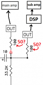
- With the goal of a WAW setup in mind, I'd like to connect a power amplifier (main speakers) and also a DSP unit + subwoofer amplifier to the output of the preamp. Does this change (or halve or double) the required value of the output resistor (for example 2 times 50k) ? Or leave it like is? What effect would it have?
- In order to add the effects of a 1st order line-level passive high-pass crossover (LLPXO) to the main speakers, should one simply add a capacitor in front of the 100 ohm resistor (and tailor the value according to the 100 ohm load it sees) ? Does that affect the signal that the DSP unit sees or needn't we worry about that?
Have a nice day, thanks in advance, cheers
Attachments
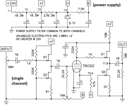
The 100k pot will work, but the HF bandwidth will decrease at higher volumes, compared to the 50k pot.
It will allow about half the HF bandwidth in the worst case.
The 10uF output blocking capacitor may have to be increased depending on the values of the input impedances
of the amp and DSP, or the bass will roll off earlier. The series 100 ohm resistor is a very minor factor compared to
those input impedances, and can be neglected.
For a passive high pass filter, the series capacitor is calculated based on the total resistive load to ground.
The 100 ohm resistor is a very minor factor (and can be neglected), compared to the amplifier input impedance.
Does this mean that mostly the input impedance of the main amp determines the total resistive load to ground, that forms the basis for the calculation of the high pass series capacitor?For a passive high pass filter, the series capacitor is calculated based on the total resistive load to ground.
The 100 ohm resistor is a very minor factor (and can be neglected), compared to the amplifier input impedance.
Essentially, but to be exact the resistance to use is the sum of the 100R and the resistance to ground.
I would also suggest perusing this post as you're building: https://www.diyaudio.com/community/threads/b1-with-korg-triode.313612/
Is this the case because having two loads (amp+DSP) and thus generally speaking 'double' the total impedance that the output stage of the preamp sees, the capacitor may have to be changed accordingly?The 10uF output blocking capacitor may have to be increased depending on the values of the input impedances of the amp and DSP, or the bass will roll off earlier
If I understand correctly, the front end of the amp and the DSP may receive differing amounts of the preamped signal depending on the ratio between their input impedances. For example, the DSP may be loaded a little higher, or more likely, vice versa ?
Thank you! I've read this pdf a hundred times already. Each time comprehending just a little moreI would also suggest perusing this post as you're building:
The two loads in parallel make the total load smaller, but the two loads will receive the same signal voltage.
The source current does share depending on the relative load impedances. If the combination is 10k or higher,
then the 10uF capacitance is still fine.
The source current does share depending on the relative load impedances. If the combination is 10k or higher,
then the 10uF capacitance is still fine.
- Home
- Amplifiers
- Pass Labs
- Newbie questions