No matter how hard I try find an answer I'm still confused about this particular subject. 
It all comes down to grounding and the confusion sets in when I try to convert an opamp circuit to a single rail operation equivalent.
The books and other documentation that I have does provide a lot of good information, but still does not answer all the questions that I have. I some cases values of components are just thrown in without any explanation of why. Rule of thumb I guess.
I hope someone will come to my rescue.
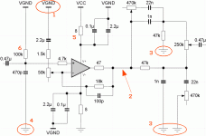
Okay, I've included a schematic with highlights of the parts that are of concern.
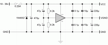
Ground is +/-0V, VCC is +30V and VGND is +15V. The virtual ground is maintained by a buf634.
Question 1a: Is it correct to connect the feeback loop to virtual ground (+15V) rather than to ground (+/-0V) ?
Question 1b: If I would connect the feedback loop to ground (+/-0V) would the opamp then operate in the non-linear region ? (Compared the two an did not notice any difference in sound.)
Question 2: What DC level should I expect at the output of the opamp relative to ground (+/-0V) ? (I assume +15V.)
Question 3: The opamp is driving a tone control made up by a low-pass and high-pass filter. I'm not sure, but I think the grounding points are incorrect. Shouldn't these be connected to virtual ground (+15V) instead ? (My thinking was that the opamp, fed with a sinewave, would not be able to draw any current half of the cycle since the ground point of the opamp is at the same level as the source.)
Question 4a: The 470 pF capacitor at the input is supposed to filter out unwanted RF noise. Is it correct to connect this capacitor to ground (+/-0V) rather than to virtual ground (+15V) ?
Additional ponderings...
Question 4b: How does this capacitor affect input impedance ? Does it in essence set the input impedance ?
Question 5: What would be a proper magnitude of the decoupling resistor ? With the values provided the corner freq. would be about 8.6 kHz.
Question 6a: What would be a proper magnitude of the resistor ? (I've seen values from 0 Ohm to 1 MOhm.)
Question 6b: Does the 100kOhm resistor set the input impedance ? If not, does it affect input impedance ?
/nosy
Attachments
As long as the virtual ground in your circuit has the DC value
which biases the op amp (+ input) into the region you want
and otherwise has the AC character of ground, it should
not be an issue. You don't show where the output ultimately
goes, but you will want to consider whether to cap couple it,
as the output has a DC value referenced to real ground.
Often as not, for a simple circuit, I make virtual ground out of
two resistors and a capacitor to ground. 😎
I will probably leave out the output cap
of this stage, but the output stage of
the entire circuit will certainly need an
output cap.
of this stage, but the output stage of
the entire circuit will certainly need an
output cap.
Guess I'll have to draw most the of conclusions meself...

Indeed it may work, but then some other configuration
may work fine too... What is the correct way? I won't give
up... yet.

Indeed it may work, but then some other configuration
may work fine too... What is the correct way? I won't give
up... yet.
- Status
- Not open for further replies.
- Home
- Amplifiers
- Solid State
- newbie questions

