Hi,
For a preamp, what is the purpose of the 4.64K series resistor on each input signal before it enters the amp circuit first valve?
Does it have to be there, why 4.64K and could it be slightly different value etc.
Thanks,
For a preamp, what is the purpose of the 4.64K series resistor on each input signal before it enters the amp circuit first valve?
Does it have to be there, why 4.64K and could it be slightly different value etc.
Thanks,
For a meaningful answer schematics is needed.Hi,
For a preamp, what is the purpose of the 4.64K series resistor on each input signal before it enters the amp circuit first valve?
Does it have to be there, why 4.64K and could it be slightly different value etc.
Thanks,
ahh ok
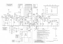
Here you go. if you follow the diagram, all of the R14, 15, 16, 17 are 4.64k and then R19 is also 4.64k, which by my logic the signal then also passes through?
I am fitting a bypass to miss the balance control and the mode selector and taking the signal from either after or before this R19.
Thanks,
I only think this question makes sense....
Attachments
Bit hard to follow the signal path but best guess is the 4k6 is to trim IP gain as it forms a potential divider with the pot. Suppose it also stops the IP acting as an arial, stops picking up stray RF.
Doesn't have to be a 4.6443434 0.001% resistor, that's just daft. Perhaps the builder/designer had a few 1000 spare or put them in to bamboozle potential buyers, "oooh look, high precision resistors, must be a high precision preamp then"
Andy.
Doesn't have to be a 4.6443434 0.001% resistor, that's just daft. Perhaps the builder/designer had a few 1000 spare or put them in to bamboozle potential buyers, "oooh look, high precision resistors, must be a high precision preamp then"
Andy.
That's an ARC design. An (IMO) undesirable characteristic of ARC designs is complexity for its own sake. 😡
so the question remains, can I skip this in series R19 resistor or is it too complex a circuit to answer?
interestingly the SP10 has a phon bypass switch (my friend has one) and his phono sounds way better with the bypass operated. It skips the selector switch too - but does not run through a 4k6 resistor in the config, hence my intrigue 🙂
My simpleton logic is that each signal comes in via a 4k6 (R14,16,17) then also goes through another 4k6 (R19) before passing through selector and balance then volume pot.
So if balance is set to centre then the two 4k6 are just really adding to the attenuation of the pot divider circuit.
So then why not remove R19 and use the pot to attenuate the output, or as asimple logic question for cost and simplicity why was the circuit not build with R14,15,16 not included and then R19 at 9k2??
Hope this makes sense to anyone, just trying to learn!
"That's an ARC design. An (IMO) undesirable characteristic of ARC designs is complexity for its own sake" Yep.
First off you don't need to use a 1% part."So then why not remove R19 and use the pot to attenuate the output" yes you can skip them,maybe. The answer is to build the circuit on the bench first on a breadboard, but as mentioned previously having no resistor may mean you pick up stray RF etc. With no resistor you have a long bit of wire, an arial in effect.
On a lot of preamps the signal comes in via the RCA, then goes into a trimmer or two fixed resistors so you can balance all the various IP's to the same level prior to entering the preamp proper.
A warning, the wiring going into a preamp if not done right will introduce hum, you only need about 2mV of 50hz/60hz on the grid of the first valve to have a big problem.
Andy.
ahh ok
Here you go. if you follow the diagram, all of the R14, 15, 16, 17 are 4.64k and then R19 is also 4.64k, which by my logic the signal then also passes through?
I am fitting a bypass to miss the balance control and the mode selector and taking the signal from either after or before this R19.
Thanks,
I only think this question makes sense....
It appears to me to be the load on unselected inputs. The input switch shorts all unselected inputs to ground and
only allows the the selected input to pass through. If you actually have the unit and not just a schematic, you can
easily verify this with an ohm meter. All inputs should read 4k64 to ground EXCEPT the selected input. No source
ever sees a load less than 4k64.
G²
- Home
- Amplifiers
- Tubes / Valves
- Newbie question - sure it's obvious...