My eTracer (curve tracer) has a handy load line calculator that lets you try many operating points with the tube you just traced with direct reading of distortion at 2,3,4,5 etc. I'm playing with a 6CG7 trying many different operating points but staying at 250v plate voltage. I tried 27K, 33K, 47K, and 62K plate resistors at currents ranging from 5ma to 11ma (staying under the max power curve). So basically examining hundereds of operating points, seaching for a point I like based on distortion. But I dont really know what I like because I'm a beginner.
I do know that "odd harmonic bad" "even harmonic good" so in varying the ma and plate load resistor I went off in search of points where the 2nd harmonic became greater than the 3rd. I did find operating points where that happened, but more often the 3rd harmonic exceeded the 2nd and often they were pretty much equal.
My question... If the designers goal is for a pleasing harmonic profile should he be searching for the operating points where the 2nd harmonic pops out a little above the 3rd? Or simply the point with the lowest THD? I did find that the higher plate load gave the lowest THD overall and also I'd find more points where the 2nd exceeded the 3rd therein. In all cases 4th, 5th harmonics were proportionally very low so I didnt consider them. How do you do it (select operating points) if the criteria is to be distortion?
Windcrest77,
That is a great question!
I hope we get some opinions from others on what amplitube ratio of 2nd to 3rd harmonic distortions listeners like best.
This is the Heart of your post.
But once we get an answer, we have some more questions to answer.
Start with a tube that is adjusted to that "ideal" ratio.
For example, what if the ratio is 15dB more 2nd that 3rd?
Use a couple of tubes that at some signal level have 15dB more 2nd harmonic than the 3rd harmonic.
One is a driver tube, and one is an output tube.
Suppose you use those two tubes in a 2 stage single ended amplifier; and at some level, the driver stage has 0.5% 2nd harmonic distortion, and the output stage has 0.5% 2nd harmonic distortion.
Because the driver and output stages are of opposite phase, most or all of that 2nd harmonic distortion is cancelled.
This is an effective serial 2nd harmonic cancellation.
The 3rd harmonic distortion is not cancelled.
That is sometimes only accomplished in an extreme case, but some designers aim to do it that way.
One of the problems of that single ended amp (cancellation) scheme, is that the driver tube is driving a fairly constant load impedance across the audio frequency range, so its second harmonic distortion is relatively constant versus frequency.
But, the output tube is driving a widely varying load, due to the loudspeaker's varying impedance across the audio frequency range. That varying load causes the 2nd harmonic distortion to change amplitude (%), versus the frequency.
So the two stage single ended amplifier's2nd harmonic distortion cancellation is good at some frequencies, bad at other frequencies, and partial at other frequencies.
Then there are other circuits that have different 2nd and 3rd harmonic ratios, versus the 2nd/3rd ratio of a single tube.
A Push Pull output stage is one example.
A phase inverter that uses a current sink in the coupled cathodes is another example.
Both of those circuits tend to cancel all or most of the 2nd harmonic distortion that each tube produces.
The 2nd to 3rd distortion ratio of a single tube is not the same as either of those two tube circuits.
The cancellation of the 2nd harmonic distortion, is because of the push pull nature, or the differential nature of those topologies.
Last edited:
Both HDs rise with level.
3rd HD starts lower but rises faster than 2nd HD.
If you only listen to test tone you can pick your flavor.
If you listen to music the 2nd is usually larger but still small, up to high output when 3rd catches up and dominates.
Pick your plate resistor smaller than your load resistance. (You do know the load resistance has to be considered?)
Pick your B+ as high as convenient. At some point like 250V or 350V the costs rise radically for little incremental benefit. But if you have 500V coming out of a power amp, 420V to the last stage of a preamp is not wrong.
Bias as close to zero-grid without causing the peak signal to approach grid current.
Both HDs rise with level.
3rd HD starts lower but rises faster than 2nd HD.
If you only listen to test tone you can pick your flavor.
If you listen to music the 2nd is usually larger but still small, up to high output when 3rd catches up and dominates.
Pick your plate resistor smaller than your load resistance. (You do know the load resistance has to be considered?)
Pick your B+ as high as convenient. At some point like 250V or 350V the costs rise radically for little incremental benefit. But if you have 500V coming out of a power amp, 420V to the last stage of a preamp is not wrong.
Bias as close to zero-grid without causing the peak signal to approach grid current.
Great, I observed all you mentioned... 3rd did rise faster, 2nd never departs a whole lot from 3rd, there are many more op points where 3rd exceeds 2nd but if you look long enough you'll find he ones where 2nd pops. Yes the load resistor is to be bigger than plate but this tool has no next stage load setting, low impedance should always feed matched or higher right? Its my understanding the load resistor in parallel with the plate drops the resistance and that value is what you use to draw the AC load line, which will be more vertical, i haven't begun to figure out AC lines yet. On the grid I did observe that biasing more to the left kept me out of where the curves all tighten up on the right, so that makes sense. Thanks.
Windcrest77,
That is a great question!
I hope we get some opinions from others on what amplitube ratio of 2nd to 3rd harmonic distortions listeners like best.
This is the Heart of your post.
But once we get an answer, we have some more questions to answer.
Start with a tube that is adjusted to that "ideal" ratio.
For example, what if the ratio is 15dB more 2nd that 3rd?
Use a couple of tubes that at some signal level have 15dB more 2nd harmonic than the 3rd harmonic.
One is a driver tube, and one is an output tube.
Suppose you use those two tubes in a 2 stage single ended amplifier; and at some level, the driver stage has 0.5% 2nd harmonic distortion, and the output stage has 0.5% 2nd harmonic distortion.
Because the driver and output stages are of opposite phase, most or all of that 2nd harmonic distortion is cancelled.
This is an effective serial 2nd harmonic cancellation.
The 3rd harmonic distortion is not cancelled.
That is sometimes only accomplished in an extreme case, but some designers aim to do it that way.
One of the problems of that single ended amp (cancellation) scheme, is that the driver tube is driving a fairly constant load impedance across the audio frequency range, so its second harmonic distortion is relatively constant versus frequency.
But, the output tube is driving a widely varying load, due to the loudspeaker's varying impedance across the audio frequency range. That varying load causes the 2nd harmonic distortion to change amplitude (%), versus the frequency.
So the two stage single ended amplifier's2nd harmonic distortion cancellation is good at some frequencies, bad at other frequencies, and partial at other frequencies.
Then there are other circuits that have different 2nd and 3rd harmonic ratios, versus the 2nd/3rd ratio of a single tube.
A Push Pull output stage is one example.
A phase inverter that uses a current sink in the coupled cathodes is another example.
Both of those circuits tend to cancel all or most of the 2nd harmonic distortion that each tube produces.
The 2nd to 3rd distortion ratio of a single tube is not the same as either of those two tube circuits.
The cancellation of the 2nd harmonic distortion, is because of the push pull nature, or the differential nature of those topologies.
Thanks 6A3 a lot to chew on here but something to consider and revisit once I'm testing with two stages. I see how 2nds will cancel but 3rds not, 2nds are "in tune" octaves and the wave would find matching inverted peaks along the time axis, with 3rds not so.
Another thing to consider - there is really no point in optimising the single particular stage.
Say, in the two-stage amp ("classic" one with two inverting common-cathode stages) even harmonics partially cancel, and all the harmonics in general interact in all sorts of funny ways.
Say, in the two-stage amp ("classic" one with two inverting common-cathode stages) even harmonics partially cancel, and all the harmonics in general interact in all sorts of funny ways.
Generally, it is pretty simple. Lowest distortion is where a triode runs the hottest, voltage and current wise. Unfortunately, it is in conflict with tube's longevity and reliability.
Because distortion grows with output, the most straightforward way to reduce the former is to increase the latter. If normal listening level is 2 W, make a 20 W amplifier.
Painstaking adjustment of bias point does not make much sense to me. Cancellation of 2nd harmonic in the following stage - may be, may be, but it is not as simple as it appears.
PRR,
As always, some important points.
Thanks!
You made me think again, about 2nd order intercept, and 3rd order intercept.
Both for Harmonic Distortion, and Intermodulation Distortion.
You already know that.
. . . . But just for Newbies . . .
I used to describe 2nd order harmonic distortion this way:
One race car, "Fundamental" starts the race first, going 100 MPH (or 100 KPH).
A second race car, "2nd order" starts Much Later, going 200 MPH (or 200 KPH).
Eventually, the "2nd order" car, catches up to the "Fundamental" car.
(The Rate of Closure is 100 MPH or 100 KPH).
That is 2nd order Intercept.
I used to describe 3rd order harmonic distortion this way:
One race car, "Fundamental" starts the race first, going 100 MPH (or 100 KPH).
A second race car, "3rd order" starts Much Much Later, going 300 MPH (or 300 KPH).
Eventually, the "3rd order" car, catches up to the "Fundamental" car.
(The Rate of Closure is 200 MPH or 200 KPH).
That is 3rd order Intercept.
For Intermodulation Distortion, the Race Car Scenario is the same, except that there are two original tones:
two "Fundamental" cars, and two 2nd order cars, and two 3rd order cars.
Two @ 100 MPH; two @ 200 MPH; and two @ 300MPH, respectively.
Of course, in electronics, the signals never quite reach the Conceptual Intercept point.
Everything is clipped and limited first.
But for the linear, well behaved, signal levels, those rates of closures are true.
This is taught, and easily remembered, when shown on a spectrum analyzer.
TG,
For a 2 stage single ended amplifier, one rule some designers use is:
An extremely linear driver stage.
An output stage that trades off power, for better linearity and better damping factor.
An output stage that still has more 2nd harmonic distortion than the driver stage.
A single ended amplifier that does that has dominant 2nd harmonic distortion.
And at low to moderate signal levels, the 3rd harmonic and all of the higher harmonics fall off at an increasing rate versus the number of the order.
In other words, there is no "Funny" mix of harmonics.
How about that?
Last edited:
sser2,
You are correct.
Nothing is simple, when it comes to distortion.
The following are generalizations, but are more likely to apply, if there is no negative feedback . . .
1. Suppose an amplifier has 2nd harmonic distortion.
And, suppose a loudspeaker has 2nd harmonic distortion (they all do to some degree).
Then, depending on which polarity you connect the speaker + and - terminals to the amplifier + and - terminals, the combined amp/speaker 2nd harmonic distortion is:
Either partially cancelled
Or increased partially
. . . No magic, just simple math.
2. The distortion you get on plate curves, using a resistor for the load line is one thing,
it is a Straight Line.
The distortion you get on the plate curves, using a reactive loudspeaker is another thing,
it is an Ellipse.
3. Generally, the Elliptical load line is more of a problem for a Single Ended amplifier.
Generally, the Elliptical load line is less of a problem for a Push Pull amplifier.
4. A "special case" push pull amplifier can be designed with the same output stage, but with some 2nd harmonic in the driver stage (on purpose to change the order of the dominant distortion). That makes for two things:
Better performance with an Elliptical load line, like normal push pull amplifiers.
Dominant 2nd harmonic distortion (similar to a single ended amplifier).
You can listen and compare that "special case" push pull amp with a single ended amp.
But, one difference is the nature of the damping factor of the two amps:
Single Ended amp has a non-symmetrical damping factor.
Push Pull amp has a symmetrical damping factor.
Last edited:
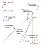
"Simple" amplifiers (generally single-ended without NFB) have super predictable distortion profiles. The RF engineers use this to simplify a wide dynamic range into just a few numbers. These "intercepts" are not real points but allow you to back-plot the distortion lines.
As you see, the ratio 2nd/3rd depends entirely on the signal level.
As you see, the ratio 2nd/3rd depends entirely on the signal level.
Attachments
PRR,
Thanks for posting the graph.
Another important point on the graph is the 1dB compression point.
That is the point where the increase of output voltage does not follow the increase of input voltage, and the output lags behind by 1 dB.
In voltage terms, -1dB, the output is lagging by 0.89, instead of by 1.0 (89% of the expected total increase).
I used to use a signal generator, 1dB and 10dB step attenuators, and spectrum analyzer to measure those aspects . . . harmonics, intermodulation products, and 1 dB compression.
Your point about single ended without negative feedback is important.
I used the words "well behaved" region, because those are where the results are as you said: "super predictable".
I believe that those well behaved super predictable regions are similar to what occurs in nature.
A loudspeaker may have similar response, until it gets near the 1 dB compression point.
I also believe that for triode push pull amps without negative feedback, similar well behaved super predictable regions exist.
Last edited:
............I also believe that for triode push pull amps without negative feedback, similar well behaved super predictable regions exist.
Yes, except the 2nd harmonic and its notional intercept are pushed "infinitely" up-right through cancellation. (Never perfect but often perfect-enough.)
A triode push pull amplifier that does not have negative feedback, may have dominant 3rd harmonic distortion.
A push pull amplifier that is designed to have dominant 2nd harmonic distortion:
I believe that purposely putting some 2nd harmonic distortion in the driver stage of a push pull triode amplifier that does not have negative feedback, can result in low to medium output signal levels that will have more 2nd harmonic distortion than the 3rd harmonic distortion, and at the same time still maintaining a fairly symmetrical damping factor.
The Paraphase inverter using two triodes, has a form of serial cancellation of the 2nd harmonic at the output of the 2nd tube in the inverter.
Both tubes create 2nd harmonic distortion, but the 2nd tube gets its signal from the first tube, and its 2nd harmonic distortion is in the opposite phase, so it cancels.
(The transfer function of the first tube is canceled by the opposite phase transfer function of the second tube).
The paraphase is purposely designed so the output amplitudes of the two signals is the same.
So, one output tube is driven by the first inverter tube that has some 2nd harmonic distortion.
But the other output tube is driven by the second inverter tube output that has no 2nd harmonic distortion.
As a result, this case of push pull amplifier has dominant 2nd harmonic distortion, until the signal level is large enough to make the 3rd harmonic distortion increase to be greater than the 2nd harmonic distortion.
Or, use a cathode coupled phase inverter with a current sink in the parallel cathode circuit. Just mismatch the plate loads, signal level of the two phases will have different amplitudes. That means one output tube will be driven harder than the other output tube. The result is that the cancellation of the 2nd harmonic distortion of the output stage will be reduced.
Again, the 2nd harmonic distortion will be dominant for low to medium signal levels.
Similarly, by using unequal resistors in a concertina phase splitter can result in dominant 2nd harmonic distortion at the amplifier output stage, just as the other 2 examples above.
Last edited:
- Home
- Amplifiers
- Tubes / Valves
- Newbie question - Selecting oper. point by harmonic dist. 2nd vs 3rd (my goal?)