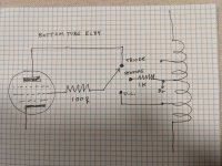
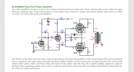
I'm breadboarding this John Broski EL84 Triode Strapped PP amp for an eventual final project. Since my OPT has screen taps I wanted to add an option for ultra linear mode, and since I'm going that far another option for pentode mode.
Did I hook this up right assuming my scribbled schematic is the bottom tube of the PP pair and the top tube would just mirror this on the other screen tap.
Is 1.1K a good value for an EL84 screen resistor here?

The project I want to modify with a screen switch:

Did I hook this up right assuming my scribbled schematic is the bottom tube of the PP pair and the top tube would just mirror this on the other screen tap.
Is 1.1K a good value for an EL84 screen resistor here?

The project I want to modify with a screen switch:

its all nicely explained in tubelab's simple SE
Schematic | Tubelab
by no circumstances do the switching while under power
Schematic | Tubelab
by no circumstances do the switching while under power
its all nicely explained in tubelab's simple SE
Schematic | Tubelab
by no circumstances do the switching while under power
Thanks,
Yeah I'm still trying to think of some kind of defeat switch where a person couldnt switch the screen grid while B+ is present.
It looks like mine is the same as Tubelab for triode and UL, I suppose my Pentode Mode should be ok as long as 1.1K is a reasonable value for the screen resistor with EL84.
I think these options sound attractive - 3 amps in 1 - but ultimately the operating point, output transformer, music source and speakers will determine the optimal setting, and that is where it will probably stay. If you use screw connectors under the hood so that reconfiguration is just to flip the amp, and move a couple of wires, then that saves a lot of complexity, and alleviates concerns about misuse of a visible switch.
1. Your schematic in post #1 does not connect the plate to the bottom of the primary.
That is where it belongs, on the same 1/2 of the primary as the screen UL tap that is also on the bottom 1/2 of the primary.
If you misconnect the screens to the wrong UL taps, you may have a power oscillator.
2. Do not do any work inside the amp bottom, unless first you check that the B+ voltage has been discharged.
3. If you do not have a Bleeder Resistor on your B+, then you need one.
Otherwise your B+ will not be discharged until you grab it . . . Ouch!!!
Prevent the "Surviving Spouse Syndrome".
Safety First!
Also, get a switch that is rated properly. Peak voltage available there will be OTO 600V. Such switches are not common until you get contact ratings *WELL past an ampere.
cheers,
Douglas
cheers,
Douglas
long time ago I did something similar, but did not use switch, just normal terminal power strip and moved the wire from one position to next
at the end it was futile exercise, everyone knows SE triode sounds best
NTE European Terminal Strip 25-E2200 12-Pole 50A
at the end it was futile exercise, everyone knows SE triode sounds best
NTE European Terminal Strip 25-E2200 12-Pole 50A
I know my schematic is crappy, it's just a sketch about the switch. I will probably just do a jumper in the chassis maybe with gold banana plugs. But at Axpona a few years ago a McIntosh was being demoed that had such a switch commercially, but maybe the presenter knew the switching procedure.
- Home
- Amplifiers
- Tubes / Valves
- Newbie question: Does this screen switch look ok?