I've tested DC offset with my cheapo DMM and I'm getting a reading of 0.0mV so I thought I'd check that I'm doing this right. I have the amp powered with no load connected and (out of the picture) I'm shorting the input terminals.
When I first switch on I get a reading of <10mV which reduces to 0 over a few seconds. Then when I short the input I get a reading of 1 or 2 mV which quickly goes down to 0.
That's exactly what I'd expect. Most DMMs aren't good enough to resolve the 50-100 uV of typical output offset on the Modulus-series amps.
Does this sound correct or should I buy another DMM to check this with?
If you have money burning holes in your pocket, I'd look at a HP/Agilent/Keysight/Whatever-Their-Name-is-This-Week 34401A. It's a 6.5 digit bench top multimeter. It'll set you back about $1200. Nice meter. I have two of them that I picked up calibrated for dimes on the dollar during the recession. The HP 3478A isn't bad either, though for measuring on tube circuits its 300 V limit can be annoying. That one is more like $150. Get a calibrated one if you go that route.
Seriously, though. You're trying to invent problems where there are none. Everything you've reported so far indicates that your amp works as designed.
Test #2 - I used REW to create a 400Hz sine wave and using the digital volume control on the miniDSP the closest I could get to 100mV was 102, this gave me 2.08V on the output with a 10W 8R2 as a load. So I guess that sounds about right.
That's within the measurement tolerances of your meter.
Test #3 - Question - how do measure whether the amp is clipping? Also I don't have a scope at the moment although I do have some software tools capable of creating square waves (REW, Reason etc.) I have no way of checking how they are reproduced at the analogue input.
If you don't have a scope you can't look at the clipping behaviour. However, as I pointed to earlier you're creating problems where there are none. Plug the amp in and enjoy the music.
...unless you're trying to learn how to test an amp, in which case you should get a scope and learn how to use it. 🙂
You can kinda/sorta test clipping my measuring the gain. You did that earlier. Input voltage: 0.102 V; output voltage: 2.08 V. Calculate the gain (Vout/Vin). Crank the input up to 0.2 V. Measure again. Draw gain vs input voltage. Or Vout vs Vin. You'll find that once you reach about 900 mV on the input, the output no longer tracks the input. I.e. as the input voltage is increased, the output voltage no longer increases. That's hard clipping. To look at the clipping behaviour, look at the output on a scope.
I'll drop off for a couple of weeks. I hope you've plugged the amp in and taken a listen by the time I come back. 😉
Tom
Last edited:
What do you do when you're waiting for your boards to arrive from China. Well if you're as anally retentive as me then creating a virtual version is a possibility. I need the dimensions to design the chassis, but couldn't help putting in a little bit extra detail.
Hi simonra,
Out of curiosity what software did you use to render...i like it?
Hi simonra,
Out of curiosity what software did you use to render...i like it?
Hi,
I use Fusion 360, it's free for hobbyists / non-professionals although that's not obvious from the landing page - if you download the demo version and read through the license info you can apply for a license annually. It's fantastic, I've used it to model the whole amp chassis, the top and bottom panels are being laser cut and the front panel and volume knob are being cnc'd - I just sent the manufacturers STP files from fusion.
Finally Done!!
Hi,
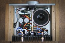
Just a quick update... I finally finished the amp today and gave it a good listening to. Very happy with the results, without further measurement I can't say for sure how good it is but in comparison with my UCD180 set-up it certainly stands it's ground sounding smooth, controlled and open. I wan't sure whether it'd have enough power but it's loud enough through my Seas A26 speakers (88dB sensitivity).
Starting on a phono stage next, thinking of using the LME49710... I'm storing up all my dumb questions to start another thread on that.
Here are a few pics...
Hi,
Just a quick update... I finally finished the amp today and gave it a good listening to. Very happy with the results, without further measurement I can't say for sure how good it is but in comparison with my UCD180 set-up it certainly stands it's ground sounding smooth, controlled and open. I wan't sure whether it'd have enough power but it's loud enough through my Seas A26 speakers (88dB sensitivity).
Starting on a phono stage next, thinking of using the LME49710... I'm storing up all my dumb questions to start another thread on that.
Here are a few pics...
Attachments
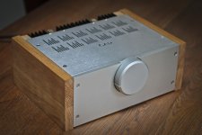
About as compact as could be, love it! Have you got a fuse for the mains hidden away in there somewhere?
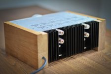
I have had a heat sink kicking around for a while that might lend itself to your chassis style. I doubt I can cut metal as sharply as yours though.
Thanks John. I've not put a mains fuse in the box yet, I was thinking of going for an in-line fuse holder like this, it's described as an 'automotive fuse holder' but it's rated at 250v so I guess it should be okay.
I would recommend to use inline fuse holder with solder lugs instead of screw type to prevent accidentally pulling live wire out of the fuseholder.
Trickiest bit with the heatsinks was tapping the M3 holes in the top and bottom - I ended up buying a pillar drill to do the job, was fairly straight forward after that.
Chassis top and bottom covers were laser cut by lasermaster.co.uk, not as expensive as you might think; the front panel and volume control were cnc'd, they were a lot more expensive but I managed to get a decent price from starrapid.com, brilliant quality.
Chassis top and bottom covers were laser cut by lasermaster.co.uk, not as expensive as you might think; the front panel and volume control were cnc'd, they were a lot more expensive but I managed to get a decent price from starrapid.com, brilliant quality.
I would recommend to use inline fuse holder with solder lugs instead of screw type to prevent accidentally pulling live wire out of the fuseholder.
Thanks, that would probably be better; I'll carry on looking for something suitable. Think I might buy these ones anyway and see how much strain they gan take.
Not seen Lasermaster before, thanks for that.
A pillar drill is money well spent, an essential item for everything other than stamp collecting.
A pillar drill is money well spent, an essential item for everything other than stamp collecting.
A pillar drill is money well spent, an essential item for everything other than stamp collecting.
I wholeheartedly agree. I use my pillar drill (aka drill press on this side of the pond) all the time.
Tom
- Status
- Not open for further replies.
- Home
- Amplifiers
- Chip Amps
- Newbie LM3886 Circuit