Hi, I’m a total newbie to diy audio and this is probably a very basic question.
I need to short a jumper on a DAC board but there are no pins on the jumper. Is it ok to put a blob of solder between the two terminals, or is there some other technique that should be used to short the jumper?
The background to this is....
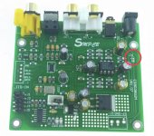
I’m building a raspberry pi-based network streamer and DAC. I bought a ESS9038 board from eBay, which supports 2 power supplies, but I’m only going to use 1. The instructions from the seller are, “if you run on regulated DC voltage single 15V, you need short J6 on DAC”.
Photo attached with the jumper highlighted. Below is a link to the eBay item.
ES9038 ES9038Q2M DAC Decoder board Support IIS DSD 384KHz NEW V1.07 HIFI AUDIO | eBay
Thanks all
I need to short a jumper on a DAC board but there are no pins on the jumper. Is it ok to put a blob of solder between the two terminals, or is there some other technique that should be used to short the jumper?
The background to this is....
I’m building a raspberry pi-based network streamer and DAC. I bought a ESS9038 board from eBay, which supports 2 power supplies, but I’m only going to use 1. The instructions from the seller are, “if you run on regulated DC voltage single 15V, you need short J6 on DAC”.
Photo attached with the jumper highlighted. Below is a link to the eBay item.
ES9038 ES9038Q2M DAC Decoder board Support IIS DSD 384KHz NEW V1.07 HIFI AUDIO | eBay
Thanks all
Attachments
Use a solder blob if you require a short circuit and have no 402 type zero Ohm links.
Surface Mount Fixed Resistors
Surface Mount Fixed Resistors
Last edited:
If you are not comfortable blobbing, use a piece of bare solid sire, like a resistor lead. Hold it across the two pads and solder/tack it down, then cut off the excess wire.
It is definitely ok, if you will do that connection only once (or two-three times).Is it ok to put a blob of solder between the two terminals, or is there some other technique that should be used to short the jumper?
A special jumper is needed only if you will need to change it over time.
J6 on the photo definitely looks like it wants to be soldered by a big blob of solder.
Another technique is a 6-inch piece of wire. Tin the end and bend the last mm at 45 degrees. Hold the far end, lay that bent part across the solder points, and touch the iron to it. Inspect, then clip the excess 5.9 inches off.
In the most cases, also a low value resistor may be used. Say, a 1Ω or 2.2Ω of the proper size may be used, with good appearance.
zero ohm resistors are normally used for this. Or cut a rectangle from copper foil, which is the same thing without '0' screen printed on!
a Zero Ohm resistor is nothing more than a length of wire with a resistor body molded to it. Before surface mount, the auto insert machines would install them just like resistors.
The common joke was: Is that a 1% or 10% Zero Ohm resistor?
The common joke was: Is that a 1% or 10% Zero Ohm resistor?
You can use something like this and use a motherboard jumper to connect them
pcb terminal strip - Bing
pcb terminal strip - Bing
- Home
- Design & Build
- Construction Tips
- (Newbie) How to short a jumper