This is your file.

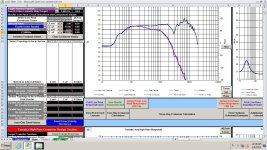
This is the output of diffraction simulator on my baffle board.

And this is the merger output.

From upper i think my merging method is wrong. Do i really need to do it? I mean output of diffraction simulator seems preety good to me. With a tweeter Xover at about 1k it would not be that bad, correct me if i am wrong. Ill come back tomorrow.
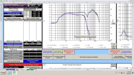
This is the output of diffraction simulator on my baffle board.
And this is the merger output.
From upper i think my merging method is wrong. Do i really need to do it? I mean output of diffraction simulator seems preety good to me. With a tweeter Xover at about 1k it would not be that bad, correct me if i am wrong. Ill come back tomorrow.
Design you box in 2pi, save SPL/Z

Design you baffle and export the diffraction responses at 10m / 1m

Export full space responses

Merge NF and FF (if necessary, adjust the level of the LF part)

Design you baffle and export the diffraction responses at 10m / 1m
Export full space responses
Merge NF and FF (if necessary, adjust the level of the LF part)
This will be of huge help many thanks. Tomorrow i will repeat steps and se if i get the same, a BIG thank you all.
I would say that my 4th order sim, that was done without a baffle correction, is darn near perfect after the baffle effect is applied. That was the point I was trying to make early in the thread.
Now simply add a tweeter crossed at 2.5k to match the woofer at 85dB.

baffle simulations assume the driver is a point source that radiates the same in all directions. real drivers don't work that way.So RS225 on that baffle actually makes sense.
an optimum design is when the driver is the same width as the baffle.
this is why vandersteen used narrower baffles for smaller drivers.
the legendary B&W nautilus took Vandersteen concept further:
by eliminating the baffle completely.
but that's not the only way to do a speaker, and in fact not the preferred way. the preferred way is this:
tweeter and mid are in custom waveguides and the speaker is designed to flush mount into a wall, again eliminating the baffle.
whereas the Nautilus is a work of art the Genelec is an industry workhorse.
of course most of us don't own a million dollar recording studio and don't have the luxury of flush mounting our speakers into a wall ... but we can learn something from both of these elite designs ...
note the width of waveguide on the Genelec roughly matches the width of the woofer ... this is what ensures good power response ( response averaged from all angles )
the mid and tweeter section is rotatable by 90 degrees so the speaker can be installed with woofers on the side rather than bottom to further match the directivity of low and mid sections horizontally and vertically ...
just because your speaker won't be on the level of these two doesn't mean the same laws of physics don't apply to your speaker ... you just have lower standards because you don't expect anybody to pay tens of thousands of dollars for your speakers ...
but you can still optimize directivity and baffle step by:
1 - using waveguide on tweeter of approx the same diameter as your midrange
2 - using woofer size of approx same width as your cabinet baffle
this assumes a 3-way of course.
by all means get the software to work correctly first, but the software can only tell you how to design the crossover for drivers you already picked in the enclosure you already have. it can't tell you what drivers to pick or what enclosure to design.
i understand you want to use your existing enclosure and that's fine. but in the future hopefully you will build your own enclosures, in which case you might want to try the vandersteen approach. this will also allow you to align the acoustical centers by moving the mid and tweeter enclosures back. theoretically you want to align the domes and dust caps in the same plane. the Nautilus doesn't do this for aesthetic reasons but Genelec does.
Last edited:
After that "exercise", try this woofer filter in the same way. This one crosses at 1.5k.First thing when i finish my job tomorrow!
Attachments
does that say 8th order ?If you are still concerned adout breakup, try matching a tweeter to this.
to be implemented passively ?
there is a saying in Russian that translates as "a cheap man pays twice"
it is equivalent to American saying "buy once cry once"
imagine "saving money" by buying a Dayton driver and then having to build an 8th order crossover to make it work.
this is like buying an Electric Car to save on gas and then having to pay $30,000 to replace the battery.
of course if going DSP route then there is no extra cost to 8th order XO but that is moving goal posts.
i have never seen any credible system using PASSIVE crossover of higher than 4th order. in fact i have never seen any credible system using analog crossover of 8th order - passive or active. i have only seen those slopes in DSP systems.
and if going to such steep slopes using DSP you should probably go with linear phase FIR.
also remember that even brick wall FIR DSP filters can't stop harmonics generated by the driver itself. this particular driver isn't that bad but i generally like to avoid any driver with huge rise in response close to the crossover because that's where harmonics can show up even with steep filters.
essentially an acoustical low pass is better than electronic because it also filters out the harmonics. in a Danley Unity / Synergy horn there is acoustical low pass in form of a baffle blocking drivers with a hole in it, but it can also be in the form of damping in cone diaphragm or surround. luckily this driver does seem to have a fair amount of damping in the surround.
Last edited:
Nonsense. It's a piece of cake. (developing on temp25's work, of course)extra cost to 8th order XO
Your simulations should look a lot like this...a real RS225-8 measured 0-180 degrees in 10 degree increments, on a 10-1/2 inch wide baffle with 1-inch roundovers, merged with nearfield.

And actual measurements of the finished speaker...approx. LR4 at 1.4kHz.

And actual measurements of the finished speaker...approx. LR4 at 1.4kHz.
what is happening starting from 250 hz ? are those suspension resonances ?Your simulations should look a lot like this
and the stuff around 1 khz - is that baffle effects ?
the zig zag between 2 and 7 khz i am assuming is cone breakup.
are you sure these are actual measurements and not simulation ? the lines below 100hz track each other way too perfectly for this to be real measurements. and the baffle anomaly around 1 khz seems too extreme - as if a point source of zero diameter was modeled rather than a 8" diameter piston.
Below about 250Hz is nearfield merged - so it is 19 actual measurements from somewhere around 250 and up merged to the same nearfield which is why they track so closely from 200Hz and below.
1.4kHz bump is baffle diffraction, almost exactly what the VituixCAD diffraction simulator predicted.
The "bunching" between 2kHz and 4kHz is just the non-waveguided tweeter on the relatively wide baffle.
Woofer breakup is down 40dB+.
1.4kHz bump is baffle diffraction, almost exactly what the VituixCAD diffraction simulator predicted.
The "bunching" between 2kHz and 4kHz is just the non-waveguided tweeter on the relatively wide baffle.
Woofer breakup is down 40dB+.
interesting. i kept telling myself baffles aren't such a big deal if prosound speakers are all square. but they are just square because it's the only practical shape - not because baffle diffraction isn't real.
it's almost like we're just kidding ourselves with trying to get on-axis measurements flat. if there is over 20db of aberration in off-axis response what difference does on-axis response make in a room where most of what we hear will be reverberant field and not on-axis response.
with a speaker like this you would have to put in half a thousand dollars into sound absorbing room treatments.
i also thought waveguides were to control power response but now that i think of it the benefit of not allowing much energy to hit the baffle edge directly may be equally if not more important.
With what tweeter is this?Your simulations should look a lot like this...a real RS225-8 measured 0-180 degrees in 10 degree increments, on a 10-1/2 inch wide baffle with 1-inch roundovers, merged with nearfield.
View attachment 1431799
And actual measurements of the finished speaker...approx. LR4 at 1.4kHz.
View attachment 1431801
Design you box in 2pi, save SPL/Z
Design you baffle and export the diffraction responses at 10m / 1m
Export full space responses
Merge NF and FF (if necessary, adjust the level of the LF part)
Thank you for all info, just one question. How do i merge diffraction and full space for a tweeter then?
I get this SPL response for RS225 which should be good.
- Home
- Loudspeakers
- Multi-Way
- Newbie Help - Designing 2 way speakers