Valve pre-amp
Nuuk,
The circuit you show has been deliberately designed to have high gain, but you could reduce this by having attenuator resistors and/or variable resistors (volume controls) in either the input or output. Remember the output impedence is very low, so it would match transistor amps better than valve amps. The HT consumption would be very low, a few milliamps only and virtually any power supply you make up would be adequate for this. The heater supply would be 6.3 volts at 0.3 amps or 12.6 at 0.15 amps, as the valve you would probably use (in the UK probably an ECC81 or ECC83) can be wired for either.
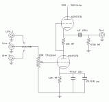
5687 circuit
Thanks for the replies lads.
Ultrachrome, I don't really want to go with a kit as cost is a big factor and I know that I can get more for my pound with the DIY approach although obviously it is a bit harder.
CV, at present I have a preamp with a selector switch and stepped attenuator with a solid state buffer on the output (ie no gain at all). I have a couple of microfarads on the input and output of the buffer.
That feeds into the power amp sections of two modified Arcam A60 amps via 2.4 metre homebrew interconnects. The interconnects sound good (I know I tried a lot of combinations) but have highish capacitance. The input impedance of the A60's is 20K.
That's why I liked the look of the 5687 design as it had a very low output Z. I presumed that the gain could be lowered but wondered if that would upset the other parameters.
Bournville, as has been said, there is little point in increasing gain only to attenutate it elsewhere in the same circuit and I always believe that keeping the component count as low as possible is good.
Surely I wouldn't use an ECC83 instead of the 5687? When I started this project, I had a design using an ECC83 and was told by many people that the ECC83 is a bit dated and there are many better valves available.
Anyway, from what has been said, I still like the idea of using this circuit but can somebody tell me what components to use to reduce the gain to say between zero and 10? Or even explain how the values are calculated?
ECC83
ECC83 could not amplify a fart in terms of driving a solid state amp . ECCXX series valves are not really suitable . 5687 should be fine , alternatively a design with a cathode follower output stage should do the trick
316a
ECC83 could not amplify a fart in terms of driving a solid state amp . ECCXX series valves are not really suitable . 5687 should be fine , alternatively a design with a cathode follower output stage should do the trick
316a
Valve pre-amp
Nuuk,
As a directly coupled cascade amplifier your circuit potentially as the gain of both halves of the valves times each other, so theoretically an ECC83 would have a gain of 10,000 and an ECC81 3,600. In practice of course the gain will be nothing like that, because of losses and impedence conversion, but still the gain is so high that if you want to keep it down to about 10 you may be better off with a different circuit. You could try an ECC82 as it would have lower gain and a greater power handling capability, especially as a cathode follower. As for the ECCxx series being a bit out of date, you could argue that this is true of valves generally! The ECC83 is highly respected by many valve enthusiasts, especially the Mullard types, as evidenced by their high cost and constant demand on auction sites like eBay.
If you use a single ECC82, with the first half as a standard resistance coupled amplifier and the second half as a cathode follower the gain will be quite low as the cathode follower will have no gain but voltage to current conversion as it lowers the output impedence. As an audio driver an ECC82 has the same sort of output (and this is an overall generalisation!) as a small power transistor such as a BFY51.
I'm not trying to push the advantages of the ECCxx series over any other types - all similar types should work well. I tend to use even older types, such as 6SN7GTs or 6LS7GTs or even triode connected EF86s and other types. The last amp I experimented with used an old loctal 7C6 as a cathode follower driving a transistor amp with no problems. I think you could experiment with different types of valve until you find a circuit/valve combination that suits you. Remember that valve tolerances are generally greater than transistors so you can chop and change components and values in a circuit without doing any real harm to a valve (unless you want to run an ECC83 on 600 volt HT of course!).
Bottlehead Foreplay
I am inclined to go with the Bottlehead Foreplay, it appears to be a tried and tested design and most say has good sound (which is my main priority).
At present my systems has a tendancy to bloom with the Rotel pre-amp and be a little base light with the passive., but excellent with vocals. I think my systems is fairly revelaing and not compasionate of poor recordings at all; a poor CD sounds really bad a good one sounds great, very Hi-fi but not always musical. Can someone describe the characteristics of the Foreplay.
Can anyone advise on the avaialbility of a good quality 240V transformer for the Foreplay and has anyone shipped the foreplay to the UK.
Is is possible to source all parts in the UK, I am quite good at cabinet work, could a wooden case be used exclusivly or is a metal chassis required.
Ian
Bottlehead Foreplay
Ian,
You should be able to get a transformer from Maplins - I have a catalogue (admitted it's from last year) and there is a transformer (£14) with 240v primary and 240v at 100ma + 6.3 volt secondary, more than enough for a pre-amp. However, I should think you could source everything from eBay at a lot less than $149 quoted for the amp plus postage. The 12AU7s used in the amp are the same as ECC82s (American vs European numbering systems) so look for Mullards on eBay, probably the best quality manufacture of these valves. They'll all be old stock of course, new versions are being made in Eastern Europe, but I doubt the quality is so good.
Valve Preamp
Hi Nuuk, IJHill,
I'm in the same boat in terms of planning for a tube preamp. I am currently finishing Rod Elliots P3a amp & P88 preamp.......possibly more candidates for the ugly but sounds good thread elsewhere on the site.😉
Frank posted this schematic last year on a similar thread & I've decided that it will be my introduction into tubes. I just have to finalise the other projects first or the wife will kill me.....
Maplins offer a slightly larger valve transformer than the one suggested above for £35 350V max, 250 mA max (not both at the same time) & 6.3V 7A max (Code DM54J). Probably not the cheapest, but you may be like me & have easier access to Maplins than anywhere else. The guys here can advise if it is overkill.
6SN7GT are a fiver there also for starters, NOS/more expensive tubes can always be substituted at a later date
Cheers & best of luck with the projects, let me know what you decide on
Paul
Attachments
Schematic
Do you know where I can get the schematic for the Foreplay.
Also are there any general tips regarding layout etc. I remember reading to twist the cables together etc.
Ian
Do you know where I can get the schematic for the Foreplay.
Also are there any general tips regarding layout etc. I remember reading to twist the cables together etc.
Ian
12B4A common cathode, resistive loaded
(sorry no sketch)
Rl = 10k
Rk = 520
B+ = 300V
Vg = - 11.9V
Ia = 19.8 mA
Rk unbypassed:
Zout = 3k3
Gain = 4.7 or 13.5 dB
Rk bypassed
C bypass = 100uF for F(-3dB) of 1Hz. Scale to preference
Zout = 1024
Gain = 5.7 or 15dB
Scale output cap to whatever is required for the input Z of your poweramp. If the PA Zin is high, I'd leave the cathode unbypassed. Dc filaments shouldn't be neccessary, but can sometimes make it quieter.
This is a cheap and available tube which sounds excellent.
And even better at about Va=100, Ia=30mA with a CCS for a load....
Sorry Ian, I've just seen your comment about looking into a Foreplay. I've been messing with my recalcitrant drawing software for ages....darm it.
Re: Valve Preamp
Hi Paul,
It is a bit 🙂 but not really a problem except that under the very light load of a pair of linestages, the B+ will be a bit higher, but a resistor and cap in the supply will bring it down to whatever you want. And of course it's heavier, larger and more expensive, but it gives you the option of trying lots of other designs with it later, even possibly some small poweramps.
Paulr said:The guys here can advise if it is overkill.
Hi Paul,
It is a bit 🙂 but not really a problem except that under the very light load of a pair of linestages, the B+ will be a bit higher, but a resistor and cap in the supply will bring it down to whatever you want. And of course it's heavier, larger and more expensive, but it gives you the option of trying lots of other designs with it later, even possibly some small poweramps.
Well after months of going around in circles, I'm leaning more toward the Foreplay if we can find a circuit diagram. At least it is a tried and tested design.
I do have one question though. Is it just a simple cathode follower? The reason I ask is because I have read in many places that cathode followers generally don't sound so good.
If Ian and Paul also go for this design we would have the advantage of being able to compare notes and check with each other if we get problems.
FOREPLAY
Hi,
It is indeed an anode follower followed by that cathode follower everyone hates so much.
And guess what, it's still very hard to beat for the money.
For some mods to this circuit:
VOLTSECOND
Cheers,😉
Hi,
It is indeed an anode follower followed by that cathode follower everyone hates so much.
And guess what, it's still very hard to beat for the money.
For some mods to this circuit:
VOLTSECOND
Cheers,😉
Thanks Frank.
I am a great believer in using dual mono power supplies if possible and was planning to do so with my valve preamp.
I am a great believer in using dual mono power supplies if possible and was planning to do so with my valve preamp.
Foreplay
Nuuk
I agree that Foreplay appears best solution at present.
If someone can supply a complete parts list or schematic I will look at sourcing components from either Mapin or RS to provide an order of cost. The idea of less that £149 for complete kit agrees with my present budget as an initial forray into valves.
Please let me know if you find a schematic or other info.
Nuuk said:If I have been 'listening' carefully, I understand that by changing the output cap, I can alter the output impedance.
You have not been listening carefully! 😉 The output cap controls the frequency response, not the Zo. If the next unit's input is a high impedance, then a small cap is fine. If you are trying to drive a very low impedance, such as headphones, then a very large cap - on the order of hundreds of uF is needed.
Hello Nick,
As you don't need any gain - just drive to your 20k amp, I'd suggest nothing more than a cathode follower.
Also, as this project is about having fun and getting started with valves, I'm going to suggest a slightly unusual power supply.
I'm thinking 12sn7gt (much cheaper than 6SN7) cathode follower, run at 210V (we'll see why that number is important) and 4.7mA.
4.7mA is a bit lowish for SN7, but you can use a constant current diode in the cathode for this (CFs like a high impedance below) this will also auto-bias your valve. Super simple.
You then need a 2uF or higher coupling cap (to push the LF -3db point to about 4Hz or lower).
Now, power supply - Maplins (or other) 230V isolation transformer with heater winding. Cap bridge and small maplins choke will give you about 330V.
Here's the cool bit - you use 2 VR105 regulators in series to get you 210V - they look cool (colourful gas discharge) and keep the supply fairly clean. Also easy to use - don't need a heater or anything.
For the whole hog, you could use octal 6x5GT rectifiers as well. All octal valves for a consistent look (they look so mcuh better than 9pin types too).
Cheers
Re: Valve pre-amp
Nope. Not even close! The gain of the bottom tube sets the limit in that circuit. You'd be lucky to get 50 out of it.
bournville said:...so theoretically an ECC83 would have a gain of 10,000 and an ECC81 3,600.
Nope. Not even close! The gain of the bottom tube sets the limit in that circuit. You'd be lucky to get 50 out of it.
CV said:As you don't need any gain - just drive to your 20k amp, I'd suggest nothing more than a cathode follower.
Then what is the point? A CD player already has a low output impedence, so adding a CF circuit onto the end of it will just add noise, and lower your signal voltage by .9 or so.
You then need a 2uF or higher coupling cap (to push the LF -3db point to about 4Hz or lower).
Into what load? This is all dependent on the load. My 3db down point will not be 4Hz into a 100 ohm load.

Joel
You have not been listening carefully! The output cap controls the frequency response, not the Zo. If the next unit's input is a high impedance, then a small cap is fine. If you are trying to drive a very low impedance, such as headphones, then a very large cap - on the order of hundreds of uF is needed.
A cap DOES have an influence on the impedance!!
Simply because a smaller capacitor COUPLES the impedance worse than a big cap.
On the other hand a big cap has other disadvantages, like inductance etc..
So as usual...horses for courses.
Cheers,
Bas
Source : Alan Kimmel
Any discussion of output impedance should include the special considerations
regarding output capacitor CL. If a very low output impedance is required
across the entire audio spectrum, capacitor CL becomes a problem (regardless
of whether it is a Mu Stage or any other kind of stage). if a stage has an
output impedance of a few hundred ohms or less, then CL must be prohibitively
large (and electrolytic) to couple such a low output impedance down to 15
or 20Hz. Thus, the primary limitations on output impedance will be the size,
cost, and quality of CL. Also, charging and discharging such a high-value
capacitor through the typical grid resistor of the following rube takes a
long time.
- Status
- Not open for further replies.
- Home
- Amplifiers
- Tubes / Valves
- Newbee looking to build Valve Preamp