I am new to DIY Audio or in fact DIY electronics. Nevertheless, I want to build a ChipAmp using the LM3875TF Amps. Since I couldn't get hold of an PCB in Switzerland - and because it should be more fun - I decided to go either on stripboard or P2P.
I looked at the schematic on the data sheet of the chip and, mainly, to the instructions given by audiosector for their kit.
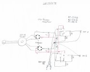
Based on that, I came up with the attached schematic. Now I would be really really grateful if someone more experienced could have a look at that. I am wondering whether having one place where all the different grounds go together (star ground?; signal and power ground?) is correct.
I also could not get hold of Caddock MK132. I have a carbon resistor (Yageo), 1/4 W, 5% or a metal foil (Royalohm) 1/4 W as possible replacements. One of these any good?
Thanks-
Benjamin
I looked at the schematic on the data sheet of the chip and, mainly, to the instructions given by audiosector for their kit.
Based on that, I came up with the attached schematic. Now I would be really really grateful if someone more experienced could have a look at that. I am wondering whether having one place where all the different grounds go together (star ground?; signal and power ground?) is correct.
I also could not get hold of Caddock MK132. I have a carbon resistor (Yageo), 1/4 W, 5% or a metal foil (Royalohm) 1/4 W as possible replacements. One of these any good?
Thanks-
Benjamin
Attachments
I am wondering whether having one place where all the different grounds go together
(star ground?; signal and power ground?) is correct.
Use power supply bypass capacitors on pins 1 and 4, 10uF//0.1uF on each, mounted close to the IC.
Also you need a 22uF (or more) capacitor in the nfb loop between R3 and ground, to minimize DC offset.
See the data sheet for details. http://www.ti.com/lit/ds/symlink/lm3875.pdf
Point to point can be good if carefully done, but a single "star ground" is not really the best method.
That's too long a discussion for here, though. Use high quality resistors (Dale RN65C, etc.) for the nfb loop.
Check out this forum. Chip Amps - diyAudio
Last edited:
Hey Bendio,
While I am by no means an expert, I built a point to point LM3875 last week so I can at least tell you how I did it 🙂
I used the same circuit as yours pretty much, albeit with the inclusion of an input resistor because I didn't use a pot. For grounding scheme; I made power star ground directly on the capacitor leads (which were soldered together) and here I connected the speaker return and positive and negative power ground from the diode bridges. I made signal ground at the ground tab of the input RCA and here I connected R2 and R3. I connected signal ground to power star ground with a wire.
I used vero board for the rectifier diodes and omitted the two bypass capacitors altogether and mounted the 1500uF caps directly onto the IC power pins. It is easiest if you remove the NC pins apart from pin 11 and run a wire to that from the negative supply pin(4) - this makes it easier to connect the caps directly to the chip. I used a physical layout similar to this Mick Feuerbacher Audio Projects (although I am neater!) and that is where I got the ground scheme from. I built each channel on its own heatsink which I scavenged from an old Cambridge amp and I mounted the RCA's and speaker terminals on it such that I could make all the connections to them using the leads from the resistors.
I would not worry too much about the resistor types for a first go - keep it cheap in case you blow it up 😉 I used 0.6W Vishay metal films 1% and it sounds pretty good to my ear. I've just built up Audiosector's kits with Caddocks so I'll compare the sound of both approaches.
I'll try and post a picture later today if I can.
Good luck, take your time, measure the offset (with the input shorted) before you attach the speakers and use a bulb tester first time you crank it up.
I also used p2p to build by setup, but not sure I would do it again like that.
Using a not too big stripboard can make your life lot easier. Specially if you are new in DIY. As Reservoir caps are about 10cm from the chip, I only used 100nF smoothing caps on the chip. Also as rayma mentioned, used a cap after R3.
Many schematics suggest to use inductor+resistor on the output, but I also left it out.
Thanks Rayma for your suggestions. If I keep power ground and signal ground at two physically different points (like tonga did) - where would these capacitors connect to?
Hi tonga,
thank's for all the information you provided!! It would be great to see some pictures!
Did you include some kind of "safety earth connector" as suggested by Decibel Dungeon (Building a Gainclone chip amp power supply.)?
And is it correct to connect the earth from mains to the chassis and then have a connection to power ground??
Hi again,
For the purpose of my test rig I did not employ a safety earth - the circuit is just mounted onto the heatsinks and is a very temporary proof of concept that only I have access too. However I do (and everyone must) use safety earth when making a more permanent home for my stuff. If you look at Peter Daniel's instructions for building his kit you'll see that he connects safety earth (from the mains) directly to the chassis he uses, he then connects power ground to the same point (this is his test set up). You may need to observe specific rules about how you achieve this depending on where you live.
Here is a picture of my build.
An externally hosted image should be here but it was not working when we last tested it.
..and here is a high res close up of one channel. You'll notice that I did not remove the NC pins..I did when I built the other channel and that made it easier. Oh, and if you us terminal blocks like these always keep checking the wires are held nice and tight - they have a tendency to compress over time and become loose and if you lose a rail I think you'll get some nasty DC at the output!
EDIT: apologies to all if the image size is too big, Mods please remove if that is the case!
An externally hosted image should be here but it was not working when we last tested it.
EDIT: apologies to all if the image size is too big, Mods please remove if that is the case!
Last edited:
I connected the earth to the chassis as it gives safety, but didn't connect the earth to the ground. But on my headphone amp that originally only had 2 pin connector it collected some noise from the air. And it goes away if I touch the its chassis. So I connected the house to the earth and it is silent. I never really understood why it is good to connect the earth to the ground. Those have separate functions and you only generate ground loops.
I never really understood why it is good to connect the earth to the ground. Those have separate functions and you only generate ground loops.
Fuse blows if transformer secondary shorts to primary (transformer fails).
If no connection, fuse will not blow and you have the mains at the amplifier output.
Finally an explanation that makes sense. I've been reading here 8 years. None of my pre 1980 amps have this connection. The post 1980 amps do, which can make ground loop hum without a differential input op amp. Differential input circuits were very expensive in 1961.Fuse blows if transformer secondary shorts to primary (transformer fails).
If no connection, fuse will not blow and you have the mains at the amplifier output.
Last edited:
If you want any hope of reproducing the performance listed in the data sheet for the LM3875, you need to have a low-impedance (low resistance, low inductance) connection from the quiet signal ground to the ground terminal on the output connector. This means short, wide connections from R3 to the output ground and from the pot and input connectors to the output ground.
Using a star ground like you've shown greatly increases the inductance of the signal ground and causes a rather dramatic rise in THD beyond a few hundred Hz. I've posted a bunch of data in this thread: http://www.diyaudio.com/forums/chip-amps/252436-lm3886-pcb-vs-point-point-data-3.html#post3846783
Tom
Last edited:
Use power supply bypass capacitors on pins 1 and 4, 10uF//0.1uF on each, mounted close to the IC.
Also you need a 22uF (or more) capacitor in the nfb loop between R3 and ground, to minimize DC offset. [...]
[/url]
If you want any hope of reproducing the performance listed in the data sheet for the LM3875 [...]
Tom
Thank you guys for the input. It's a great help to me!
What Tom said about performance related to grounding issues: do you regard the power supply bypass capacitors and those in the nfb loop, suggested by rayma, as equally important?
Gesendet von iPhone mit Tapatalk
I used a physical layout similar to this Mick Feuerbacher Audio Projects (although I am neater!)
Agreed! 😉
Thanks for the photos, great help to me. And I'd be interested to know whether you hear a difference to the kit version, once you've built that!
Gesendet von iPhone mit Tapatalk
Hi Tom - I don't doubt the veracity of your statements about grounding etc, tbh it's above my current level of understanding. I built what I could by looking at other peoples designs and reading a few bits here and there and shared that with Bendio, another self confessed noob, as I thought it might help. I'll modify my P2P build using your suggestions though 🙂
Bendio - I've built the Audiosector kit now and it sounds great. It is difficult for me to compare the two approaches sound wise as I only have one traffo which I've swapped out of the P2P setup, and I don't have enough hours listening of either really. What I can say is that they both sound great compared to my MOSFET amp which I built at quite some expense 10 years ago. Both Gainclones retain the detail of that amp (which is very detailed) but seem a lot warmer and are easier to listen to, my mosfet amp sounds somewhat glassy in comparison (although it perhaps has the edge on the GC for bass oomph, but even then not by as much as I had expected). Both GC have an impressive soundstage.
I would try building it a simple as possible first and see what you think, then begin to experiment 😉
I am using Kef q300 speakers and a Marantz CD6004 as source.
What Tom said about performance related to grounding issues: do you regard the power supply bypass capacitors and those in the nfb loop, suggested by rayma, as equally important?
I'm not sure I fully understand your question. The bypass capacitors are important for stability. National/TI recommends 470 uF + 100 nF ceramic in the data sheet. I go as far as recommending a larger electrolytic can (1000 uF), a smaller electrolytic can (22 uF), and the largest X7R dielectric ceramic cap you can get your hands on that'll survive the supply voltage. I go through my reasoning on the Taming the LM3886 - Supply Decoupling page.
The cap in the feedback network and input ground should go to the quiet signal ground. The decoupling caps, power supply ground, and ground pin on the LM38xx should go to the power ground. The power ground and quiet signal ground should both be low impedance (as wide as possible --> ground planes/pours) and connect at one spot only: the ground connection at the output connector.
It's the output voltage we're trying to control here. Therefore, the output ground is uses as a reference point. Keeping the grounds low impedance (= low resistance and low inductance --> ground planes/pours) ensures that as little voltage develops across the ground planes as possible.
Hi Tom - I don't doubt the veracity of your statements about grounding etc, tbh it's above my current level of understanding. I built what I could by looking at other peoples designs and reading a few bits here and there and shared that with Bendio, another self confessed noob, as I thought it might help. I'll modify my P2P build using your suggestions though 🙂
I do recognize that I'm a bit ahead of most DIYers. It seems like a Master's degree in electrical engineering with focus on analog electronics and 10+ years of industry experience designing precision analog circuits have left an impact on me after all... 🙂 What I'm trying to do with my Taming the LM3886 pages and participation on DIY Audio is to nudge the DIYers along a bit. I'm trying to put the theory in context such that the average DIYer with some effort can gain a higher level of knowledge. I'm also trying to test various myths (such as star grounding) using theory, simulation, and measured data. I hope I come across as helpful rather than dogmatic.
How you implement your amplifier is entirely up to you. I get the most satisfaction if I lead you down the path to success. If you'd rather meander down a different path, you're certainly free to do so. Sometimes seeing really is believing. 🙂
I would try building it a simple as possible first and see what you think, then begin to experiment 😉
Building a circuit according to the instructions first is always a good starting point. You can easily verify the impact of your modifications - or test my claims - by measuring the THD using a sound card and some software. Watch the THD vs frequency curve as you move the various grounds around.
Tom
Last edited:
I'm not sure I fully understand your question.
Tom
Sorry, English is not my native tongue and so it's sometimes difficult to bring my thoughts to paper...
I tried to copy the layout from the audiosector kit. It seemed to me that this is some kind of a minimalistic version of the layout suggested in the data sheet for the IC. And I got the impression, that there is a reason (beside making it as simple as possible for NOOBS like me) for reducing the circuit to as few components as possible.
I see your advise in regard to grounding as a simple (hopefully...) way of optimizing my drafted circuit. But adding those capacitors you further mentioned makes things (a little) more complex again and I was wondering whether you see them as optional or not. If my understanding of the audiosector-kit circuit correct, those extra capacitors are actually not essential. (*bigquestionmark*)
However, since I anyway have to order a few more parts for my project, I just might add those caps to the list and see that how to cobble it all together.
Thanks again for your help!
Benjamin
Have downloaded the National datasheet yet?
That's probably the best advice. Read the data sheet - in particular the application section, so the last many pages of the data sheet. It contains all sorts of useful information on how to use the chip. You can get the data sheet from TI: Analog, Embedded Processing, Semiconductor Company, Texas Instruments - TI.com (acquired National Semiconductor in 2012).
And I got the impression, that there is a reason (beside making it as simple as possible for NOOBS like me) for reducing the circuit to as few components as possible.
The reason is probably that either the designer of the board didn't know better or they were trying to reduce the cost of the board by making it as small as possible.
I see your advise in regard to grounding as a simple (hopefully...) way of optimizing my drafted circuit. But adding those capacitors you further mentioned makes things (a little) more complex again and I was wondering whether you see them as optional or not. If my understanding of the audiosector-kit circuit correct, those extra capacitors are actually not essential. (*bigquestionmark*)
You'll find National's advice on decoupling in the data sheet. Do beware that this recommendation was made in the 1990ies and capacitor technology has changed considerably since then. That's why I put together my Supply Decoupling page. It's basically a modern take on National's recommendation.
Tom
rev.1
...getting back to my little project here...
So I read the data sheet and tried to implement your advise, Tom:
I have attached the new schematic.
There are some things I would like to clarify: in most cases where I saw those big caps (+1000 uF), people installed 4 of them - two on each rail. Now I have only one cap per type (1500 uF, 22 uF, 10 uF) per rail. Is that ok??
The small cap (10 uF) is an X7R, 50V (SMD) by the way.
The other question is: Should I add the resistor Rb 1K Ohm between Input and IC?
Thank you!
...getting back to my little project here...
So I read the data sheet and tried to implement your advise, Tom:
I'm not sure I fully understand your question. The bypass capacitors are important for stability. National/TI recommends 470 uF + 100 nF ceramic in the data sheet. I go as far as recommending a larger electrolytic can (1000 uF), a smaller electrolytic can (22 uF), and the largest X7R dielectric ceramic cap you can get your hands on that'll survive the supply voltage. I go through my reasoning on the Taming the LM3886 - Supply Decoupling page.
Tom
I have attached the new schematic.
There are some things I would like to clarify: in most cases where I saw those big caps (+1000 uF), people installed 4 of them - two on each rail. Now I have only one cap per type (1500 uF, 22 uF, 10 uF) per rail. Is that ok??
The small cap (10 uF) is an X7R, 50V (SMD) by the way.
The other question is: Should I add the resistor Rb 1K Ohm between Input and IC?
Thank you!
Attachments
- Status
- Not open for further replies.
- Home
- Amplifiers
- Chip Amps
- Newbee: LM3875TF P2P