Hi there,
I have very little knowledge of electronics (though Im learning fast 🙂 Im in the process of building my first psu. However I have a very simple question. If my transformer delivers 25-0-25v (Am I correct in thinking that this is 2x +25v as opposed to -25v and +25v?)this will then give something in the region of 35v after rectification how can I transform this into +/-35v? Im sure the answer is very simple I just can't get my poor head around it.
Any help would be gratefully appreciated
Jamie.
Hi,
I'm afraid you've got the wrong end of the stick 😉
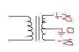
The diagram for a transformer is more helpful than the 25-0-25 description! What this means is that there are two secondary windings. One will output 25V, with respect to ground and the other will give -25V. The reason for this is that they are centrally tapped and that centre tap goes to ground. What you can do is connect ground to the bottom pin and ignore the centre one. Then you will get 50V from the top pin. (Vice versa will give you -50V) but using this method - you cannot get +-50V
I hope that is clear enough! I have enclosed a crap diagram to confuse you more!!!
Gaz
P.S. This is my first message as a Prophet! 😉
I'm afraid you've got the wrong end of the stick 😉
The diagram for a transformer is more helpful than the 25-0-25 description! What this means is that there are two secondary windings. One will output 25V, with respect to ground and the other will give -25V. The reason for this is that they are centrally tapped and that centre tap goes to ground. What you can do is connect ground to the bottom pin and ignore the centre one. Then you will get 50V from the top pin. (Vice versa will give you -50V) but using this method - you cannot get +-50V
I hope that is clear enough! I have enclosed a crap diagram to confuse you more!!!
Gaz
P.S. This is my first message as a Prophet! 😉
Attachments
Careful. The notion of + and - is not quite correct when referring to AC, since each wire goes alternately + and - depending on where you're at in the cycle. You can instead refer to phase.
Sometimes transformers have 2 secondary windings (e.g. 2x25V) and sometimes a single winding with a 'tap' in the centre (e.g. 50VCT). You can use the 2-winding version as a centre-tap version if you connect the proper wires together (getting the phase right).
Phases are normally shown as dots or absence of dots as the equivalent of +. To connect two windings in series, connect a dotted lead with a non-dotted lead (equivalent of putting batteries in series + to -).
If you take a 50VCT transformer, use a bridge rectifier and 2 filter capacitors in a conventional arrangement (see for example, the power supplies at www.sound.au.com for any of his bigger amps), you will get +/-35VDC (or 70VDC total).
Read the articles at www.sound.au.com for much more information.
Great so just to see if Ive got this right, if I connect the black and the yellow together I can use this as 0v. Then the orange would be v- and the red v+ is that about right?
Also if a transformer is said to be 18-0-18 is there anyway of knowing weather it is centrally taped or if it has two secondary windings (ie 2x25v)?? Sorry about these elementary questions but you've got to start somewhere I suppose.
Also if a transformer is said to be 18-0-18 is there anyway of knowing weather it is centrally taped or if it has two secondary windings (ie 2x25v)?? Sorry about these elementary questions but you've got to start somewhere I suppose.
Attachments
jnxw2 said:Great so just to see if Ive got this right, if I connect the black and the yellow together I can use this as 0v. Then the orange would be v- and the red v+ is that about right?
Black and yellow together forming the center tap is right. But the rest doesn't matter. It's the rectifier that establishes the DC polarity. Doesn't matter how you hook up the orange and red leads.
As someone else mentioned, dots are sometimes used on the transformer's schematic to indicate which leads have the same relative polarity. And this is important to know when you have a transformer with dual secondaries which can be wired in series or parallel.
For example, if you wanted to create a center tapped transformer, if you connected the two leads with the dots or the two leads without the dots to form the center tap, you wouldn't get any output as the two secondaries would be cancelling each other.
Similarly, if you wanted to wire the two seconaries in parallel, if you wired the lead with the dot on one secondary to the lead without the dot on the other secondary, and vice versa, you'd also get no output.
But once you've got the secondaries wired correctly, the concept of + or - is irrelevant as far as the rectifier is concerned.
Also if a transformer is said to be 18-0-18 is there anyway of knowing weather it is centrally taped or if it has two secondary windings (ie 2x25v)?? Sorry about these elementary questions but you've got to start somewhere I suppose.
Not necessarily. Some manufacturers will use the xx-0-xx format even if the transformer has dual secondaries to indicate the center tapped voltages. Though if xx-0-xx is the ONLY designation given, there's perhaps a greater chance that the transformer is internally wired for a center tap.
se
PMA said:Like this...
Right. And if you swap the red and orange leads, you get the same result.
se
Slightly off topic but...
I just bought 2 500VA transformers (TOTAL overkill...but useful for future) and a 120VA transformer, 10 Audio Grade 6800uF caps and lots of other PSU goodies...for the bargain price of...
£140!!!!!
Thanks Maplins! They make a killing out of me! If I lived in USA I'm sure I'd pay alot less!
Never mind! 😉
Gaz
PMA said:Steve,
of course. Just didn't want to confuse 🙂)
Pavel
Oh I know. I wasn't intending to take away anything from your post. I replied because your drawing helped illustrate more clearly something I'd said previously. Thanks!
se
Well I must admit I'm lost for words, I only discovered this site this morning, but the amount of replies is incredible 🙂
Thanks everyone
And now to build this thing....
Thanks everyone
And now to build this thing....
If you have a (two secondaries) transformer with unidentified leads, is it possible to determine the dotted leads with an AC signal generator and a scope?
mrothacher said:If you have a (two secondaries) transformer with unidentified leads, is it possible to determine the dotted leads with an AC signal generator and a scope?
If by unidentified leads you mean not identified in terms of relative polarity, then yes.
Just feed a sinusoid into the primary and connect the probe of one channel across the primary. It doesn't matter which primary lead you attach the probe to or which you attach the ground to. It's AC so polarity is relative. Whichever lead you attach the probe to, designate that lead as the reference. In other words, that will be the primary lead that will be assigned a "dot."
Then connect the other channel to the seconary (or one of the secondaries if the transformer has multiple secondaries). Again, it doesn't matter which lead you attach the probe to or you attach the ground to.
Using the same timebase for each channel, check the phase of the two signals. If they're in phase, then the secondary lead that the probe is attached to is of the same polarity as the primary lead that the other probe is attached to and this lead will be the "dot" lead for the secondary.
If they're out of phase, then the lead that the ground is attached to will be the "dot" lead for the secondary.
Repeat as necessary for any other secondary windings.
se
An easier way that doesn't require a scope, just a voltmeter:mrothacher said:If you have a (two secondaries) transformer with unidentified leads, is it possible to determine the dotted leads with an AC signal generator and a scope?
Apply a signal to the primary; you should be able to read voltage from both secondaries. Then just connect the secondaries in series and measure across them; if you've connected them correctly ('dot' to 'non-dot') you'll get twice the voltage. If not, you'll get close to 0.
paulb said:An easier way that doesn't require a scope, just a voltmeter:
Apply a signal to the primary; you should be able to read voltage from both secondaries. Then just connect the secondaries in series and measure across them; if you've connected them correctly ('dot' to 'non-dot') you'll get twice the voltage. If not, you'll get close to 0.
Yes, that will work as well. I gave the answer I did because the original poster asked specifically how to do it with a generator and a 'scope.
se
- Status
- Not open for further replies.
- Home
- Design & Build
- Parts
- Newbe v. simple Transformer question