Hi Guys!
OK I'm not a real newbe but lets say I'm not skilled to built regulators with transitors...
I' building a a regulator for my boss's 🙁 oldtimer. Its an old Chevy which did use 6V battery supply. Now its rebuilt to a modern 12V system.
Problem the ventilation fan still is a (very special) 6V motor. The fan motor shall stay in the car and so I looked how to regulate the supply down to 6V. The current demands are high: between 3 - 5 A. I can't use a LM317/350 it too much for them. I did not find a PWM module which is cheap enough.
So I chose to built a "Series Regulator" controlled by a Z-Diode. I thought that really simple....
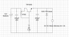
Attached is my schematic. I use a TIP 3055 and Z-Diode 7,4V (500mW).
The Tip is mounted to a heat sink. The diode get a voltage by the 470Ohm resistor.
Input and output side is stabelized by 100µF cap.
NOW MY PROBLEM: I expected appr. 7.4V - 0.7V = 6.7V on the motor. (It may drop a bit due to the load etc..)
BUT !! I get 2,7V. 😡
What would you check? What do you expect? Is the TIP 3055 maybe not the right choice or is Base- Emmitter leakage problem present? What I can say is that I have plenty of current available and the input voltage is not dropping down
OK I'm not a real newbe but lets say I'm not skilled to built regulators with transitors...
I' building a a regulator for my boss's 🙁 oldtimer. Its an old Chevy which did use 6V battery supply. Now its rebuilt to a modern 12V system.
Problem the ventilation fan still is a (very special) 6V motor. The fan motor shall stay in the car and so I looked how to regulate the supply down to 6V. The current demands are high: between 3 - 5 A. I can't use a LM317/350 it too much for them. I did not find a PWM module which is cheap enough.
So I chose to built a "Series Regulator" controlled by a Z-Diode. I thought that really simple....
Attached is my schematic. I use a TIP 3055 and Z-Diode 7,4V (500mW).
The Tip is mounted to a heat sink. The diode get a voltage by the 470Ohm resistor.
Input and output side is stabelized by 100µF cap.
NOW MY PROBLEM: I expected appr. 7.4V - 0.7V = 6.7V on the motor. (It may drop a bit due to the load etc..)
BUT !! I get 2,7V. 😡
What would you check? What do you expect? Is the TIP 3055 maybe not the right choice or is Base- Emmitter leakage problem present? What I can say is that I have plenty of current available and the input voltage is not dropping down
Attachments
470R with 6Volts across it equals 12mA. A Tip3055 has an average Hfe of 20. Therefore 20 X 12 equals a mere 240mA current and the fan draws 3Amps!
If you use a darlington pair, there will be enough gain to pass the current you require or you could use a wire wound 50Watt resistor at say 2.7R ish. Don't forget the 12V battery will have up to 14Volts on it when charging!
If you use a darlington pair, there will be enough gain to pass the current you require or you could use a wire wound 50Watt resistor at say 2.7R ish. Don't forget the 12V battery will have up to 14Volts on it when charging!
As above..
Darlington Transistor
I know it as super alfa its the same thing..
However..volt drop across device * current..how hot is it going to get?
Just be aware of it..🙂
Regards
M. Gregg
Darlington Transistor
I know it as super alfa its the same thing..
However..volt drop across device * current..how hot is it going to get?
Just be aware of it..🙂
Regards
M. Gregg
Understand HFE too low
Hi Harleyjon,
so this means I need a NPN with a much higher HFE...understand.
Then I could max the current through the resistor near 500mW of Z- Diode ( leave some safety margin of course) to reach 5A current ability.
Is this right?
Hi Harleyjon,
so this means I need a NPN with a much higher HFE...understand.
Then I could max the current through the resistor near 500mW of Z- Diode ( leave some safety margin of course) to reach 5A current ability.
Is this right?
Keep the current through the zener as low as possible..
NB you also have no current limit at start up and short/ fault conditions.
Regards
M. Gregg
NB you also have no current limit at start up and short/ fault conditions.
Regards
M. Gregg
Last edited:
It is just a fan, not a precision circuit, it doesn't need regulation. All you need is to drop about 6 volts.
If your fan draws 3 amps at 6v then you need to drop 6v at 3 amps. A 2 ohm power resistor in series? It dissipates 18 watts, so a nice 50 watt resistor ought to be OK.
Mouser: 71-RH50-2.0
$4.67 50 watt

100 watt 2 ohms were about $7.
You could play with the numbers if you like, but the fan won't much care. I am sure the fan would have worked on a low battery or on a high charging voltage, it isn't picky.
And if I made a glaring math error, let me know
If your fan draws 3 amps at 6v then you need to drop 6v at 3 amps. A 2 ohm power resistor in series? It dissipates 18 watts, so a nice 50 watt resistor ought to be OK.
Mouser: 71-RH50-2.0
$4.67 50 watt
100 watt 2 ohms were about $7.
You could play with the numbers if you like, but the fan won't much care. I am sure the fan would have worked on a low battery or on a high charging voltage, it isn't picky.
And if I made a glaring math error, let me know
Question
Hi M. Gregg,
yes its going to be hot but I've mounted it to big heat sink🙂
OK I keep the current low through the z-diode, but...
The TIP3055 has an HFE of 20 and this would mean I need 250mA through the Gate.... can you confirm? (0.25x20 = 5A)
Is a there a better transistor to use?
(I'm reading your article meanwhile - thx)
Resistor OK - but I need 3 different stages
Hi Enzo,
the Chevy hasn't got a fan regulator to control the rotation speed. My boss asked to have 3 different strenghts. So that why I thought its easier to use a transistor which can be controlled by a cheap signal rotary switch contacting three different Z-Diodes.
Of course I also thought to use a high Watt resistor before, but I assumed it would be more work to switch the high load...😱
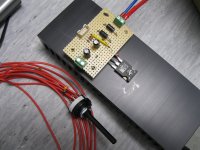
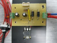
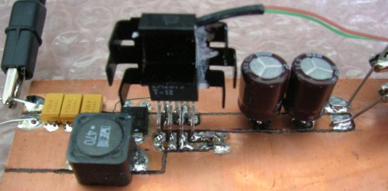
I have a pic here, pretty big heat sink 😉
(Ignore that one resistor hanging around, I used two free wheel diodes)
Hi Enzo,
the Chevy hasn't got a fan regulator to control the rotation speed. My boss asked to have 3 different strenghts. So that why I thought its easier to use a transistor which can be controlled by a cheap signal rotary switch contacting three different Z-Diodes.
Of course I also thought to use a high Watt resistor before, but I assumed it would be more work to switch the high load...😱
I have a pic here, pretty big heat sink 😉
(Ignore that one resistor hanging around, I used two free wheel diodes)
Attachments

If this is not a variable speed fan, I second this as a best solution.If your fan draws 3 amps at 6v then you need to drop 6v at 3 amps. A 2 ohm power resistor in series? It dissipates 18 watts, so a nice 50 watt resistor ought to be OK.
The circuit you have is not a good idea for heavy loads. You could use a darlington, or a FET, but the topology just isn't right for more than a 100mA, or so.
A non-regulated PWM can be made more cheaply, and almost as simply as a linear regulator.I did not find a PWM module which is cheap enough.
See example below: you can add as many speed-setting resistors as you want, or even use a potentiometer for maximum flexibility.
All the parts are cheap, common and non-critical.
In addition, it will run cool and require no or minimal heatsinking
Attachments
You might want to add a TVS or zener across the supply of the CD4000 series IC, older CMOS is sensitive and automotive environments are harsh.A non-regulated PWM can be made more cheaply, and almost as simply as a linear regulator.
See example below: you can add as many speed-setting resistors as you want, or even use a potentiometer for maximum flexibility.
All the parts are cheap, common and non-critical.
In addition, it will run cool and require no or minimal heatsinking
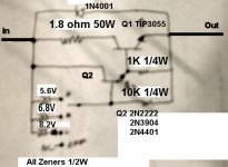
You might want to insert a 100 ohm, or so resistor in series with the collector of Q2, or tie it directly to the collector of Q1. Otherwise it could die if the output is overloaded. Even if properly fused.Here's a circuit that will do three speeds and an off, using a 4 pole switch. Adjust the zeners to get the voltages you desire. I have NOT tested this. I just drew it on as a back of the envelope type of circuit.
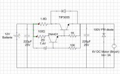
Schematics redrawn - correct?
Hi FoMoCo !
thanks alot for your suggestion! 😎
Your picture isn't so sharp - so I've put this schematic togehter. Is it correct ?
Hi FoMoCo !
thanks alot for your suggestion! 😎
Your picture isn't so sharp - so I've put this schematic togehter. Is it correct ?
Attachments
Last edited:
It's almost correct. Make sure that 1.8 ohm resistor is 25W or better. The 50W that another poster suggested is good. You can leave it out, but that shifts the heat burden onto the TIP3055. Regardless, the TIP still needs a heatsink.Hi FoMoCo !
thanks alot for your suggestion! 😎
Your picture isn't so sharp - so I've put this schematic togehter. Is it correct ?
You can use a switch to switch in different zeners for different speeds and the off position. That's what I tried to show on my circuit but, a digital photo of an envelope isn't so clear.
Also keep in mind when picking zeners that this circuit acts like one big power Zener in series. It subtracts the voltage from the supply. It's not a regulator per say. The resultant output voltage is Vsupply - Vzener - Vbe(2n4401) - Vbe(tip3055). Thus a 6.8V zener gives around 6V out with 13.8V in.
You really don't need the diode across the motor, but it won't hurt either.
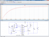
Here's a better schematic. Not all values are shown, LTSpice won't let me name a part that it doesn't have a model for. I also couldn't draw a switch. A 4 position, 1 pole, switch should be in front of the zeners.
Attachments
Last edited:
Interesting alternative !!!
Hi Elvee,
thanks to you too!! This is really a interesting alternative. I should have have seen this before 😱 I'm not sure to restart the project from scratch. But the PWM approach is the most effective of course.
🙄
Maybe I finish one first and then...Do you have an robust design in use since longer time? Since I use the circuit in a vehicle (Heat, vibration some voltage stress)
Regards
 I understand the circuit.
 Switching between three different series resistors would work just as well for fan speed control.
Resistors have the bonus of being very resistant to abuse,. Your circuit has to deal with shorts and all of the trash on the car so called 12V system, which means +/-75V transients from the alternator
Resistors have the bonus of being very resistant to abuse,. Your circuit has to deal with shorts and all of the trash on the car so called 12V system, which means +/-75V transients from the alternator
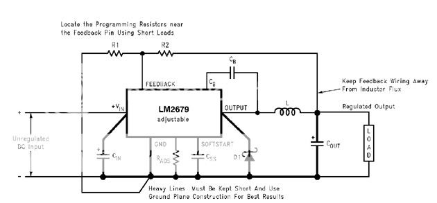
i don´t understand why people use linear regulators in hi power circuits ?
we are not in 1970 anymore
http://www.ti.com/lit/ds/symlink/lm2679.pdf
we are not in 1970 anymore
http://www.ti.com/lit/ds/symlink/lm2679.pdf
- Status
- Not open for further replies.
- Home
- General Interest
- Everything Else
- Newbe - problem with Series Reg Tip 3055 + Z-Diode***HELP**