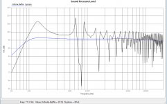
Eric, it seems like the more I read, the more I realise I don't understand. Thanks for the link to the software, it's a lot easier to quickly trial ideas than hornresp. I'm seeing what looks like a really nasty dip at 800Hz but I'm going to press on with printing one speaker and see how it sounds given that there's already so much going against this design (everything from drivers to materials) but it does fit comfortably on my printer. After that, I might look at something more conventional with well chosen components (even with the drivers I have, the Spectrum Audio beeper looks interesting). I started this project looking to make a few marginal changes to the Hexibase design which, from what I've read already, doesn't look like it was terribly convincing to start with.
Who knew audio engineering could be so hard? 🙂
Who knew audio engineering could be so hard? 🙂
Attachments
Last edited:
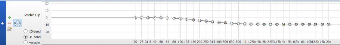
I'm seeing what looks like a really nasty dip at 800Hz...
It is worth noting that up that high in frequencies the modeler is incapable of telling you what is really happening. If you have not installed damping in th eline you can expect to see a train of pipe resonances. Th ehigher up ones are easy to kill with damping, the couple are harder to deal with (why we use restricted terminus and Zd (driver offset). A heavy taper will also shift the unwanted harmonics up in frequency which makes them a little easier to deal with.
dave
It is worth noting that up that high in frequencies the modeler is incapable of telling you what is really happening.
dave
That would explain why the default upper limit was set to 1kHz.
It's not even that accurate as T/S theory peters out at the driver's effective upper mass corner:
Fhm = 2*Fs/Qts'
Qts' = Qts + any added series resistance [Rs]: HiFi Loudspeaker Design
GM
Fhm = 2*Fs/Qts'
Qts' = Qts + any added series resistance [Rs]: HiFi Loudspeaker Design
GM
I would not completely discount a driver’s Sd or diameter being related to the TL design. It’s not a bad place to start as scaling a TL or even a BLH horn as a starting point. I have a base TL design, like the Karlsonator. The first thing I do is scale it by driver diameter just to make sure the baffle fits the driver bezel! Without that, you have no speaker. Then use that as a starting point to optimize the simulation. I have heard this “Sd has nothing to do with a TL design” repeated over and over and it’s simply not true. Another example is the FH3 - I scaled that straight down to a 3.5in driver and arrived at essentially the same design as the FH3 Lite.
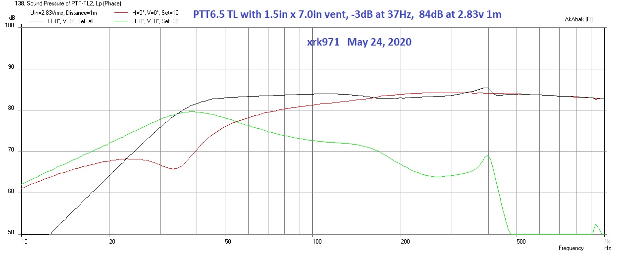
Here is the latest TL that I designed by scaling a 5.25in design up to 6.5in. The simulations worked out almost perfectly. There was just a little tweaking left to be done.
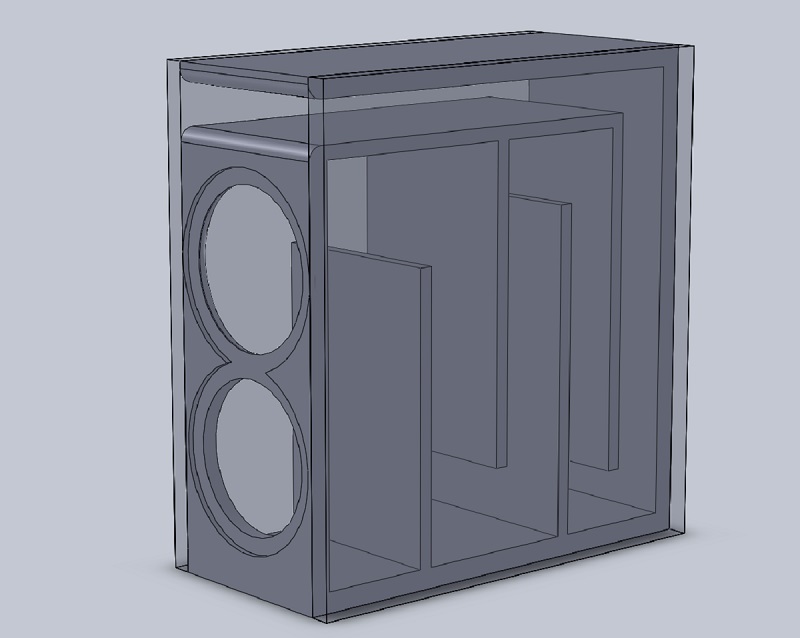
Here is the optimized simulation (very little had time be done) from the straight scaled design:
So my point is this: go ahead and scale it if the drivers are of similar Qts. Use as a starting point and adjust from there. If you can’t even fit the driver on the baffle, the design needs to be bigger.
Here is the latest TL that I designed by scaling a 5.25in design up to 6.5in. The simulations worked out almost perfectly. There was just a little tweaking left to be done.
Here is the optimized simulation (very little had time be done) from the straight scaled design:
So my point is this: go ahead and scale it if the drivers are of similar Qts. Use as a starting point and adjust from there. If you can’t even fit the driver on the baffle, the design needs to be bigger.
Last edited:
Thank you for your reply, xrk, it's funny that you mention Qts. I remembered yesterday evening that an old friend had quite a collection of handmade speakers and it was the first question he had about the drivers I'd bought. He's built all sorts of weird and wonderful TLs (I didn't recognise them as that at the time) and, when he read the specs on the Tectonics, advised me to go with a bass reflex design. Eventually, we hashed out something that looked oddly close to the SpectrumAudio Beeper (with what looks like a slightly shorter tube). Please ignore the exterior thickness on the tube, I'm going to thin it out before printing (and make it a separate piece so I can play around with an adjustable version before printing a final one). I think I'll go with this design and return to TLs in the future when I can choose more appropriate components from the ground up and build using conventional methods, since 3D printing doesn't scale well for enclosures of the required size.
Attachments

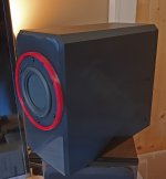
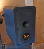
An update: I've finished the first one and, while it sounded gutless initially, there were no obvious abrupt spikes or dips (I don't have a good microphone to hand to measure them but just listened to a frequency sweep). After accidentally enabling the SPK optimise on my Denon mini hifi, they sounded quite competent so I worked out the equalisation applied by recording the response with SPK turned on and off using the headphone output and RightMark, resulting in a +9dB curve between 40 and 2.5k Hz. I'm now quite pleased with the result; they're not quite as solid on the knock test as my MA Bronze 1s but are a lot more solid than the average plastic-bodied speaker I've encountered. I think I'll have a go later in the year at something based on specifically chosen drivers rather than picking some BMRs and working backwards. Thanks again for all the help, even though I ended up going in a different direction because of my own shortcomings.
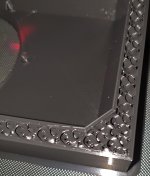
I realise I'm missing some bolts on the speaker connectors, I'm waiting for some countersunk bolts to go in their place so it's just a temporary solution. It's another 100 hours of print time for the second speaker, I've added a skirt and changed the print parameters so this one hopefully doesn't warp at the corners.
I realise I'm missing some bolts on the speaker connectors, I'm waiting for some countersunk bolts to go in their place so it's just a temporary solution. It's another 100 hours of print time for the second speaker, I've added a skirt and changed the print parameters so this one hopefully doesn't warp at the corners.
Attachments

I love these drivers, you want to get a F0 of 58hz use a 0.180cuft enclosure with 2*20mm ports 100mm long. I also used a BSC and I wouldn't describe it as gutless but instead thumpy. I did a TL as my first build ever using the TEBM65'S and was told by many the QTS was too high and honestly it was thin on the bass, so I rebuilt it
3rutu5 Bookshelf (or monitor/PC speakers?) - Techtalk Speaker Building, Audio, Video Discussion Forum
3rutu5 Bookshelf (or monitor/PC speakers?) - Techtalk Speaker Building, Audio, Video Discussion Forum
That's a really nice build, 3rutu5. My enclosure is essentially two thin (1.6/2mm, alternating walls every 0.2mm) plastic boxes connected by a 3D spring structure (gyroid infill), which might contribute but it was probably also that I'd just been listening to my main system, a pair of MA Bronze 1s backed up by a B&W ASW608. The person I gave them to was pleased with the bass (even without equalisation) so it could also be down to music tastes. I should have also mentioned that the vocal reproduction was terribly impressive.
I'm now having a go at a Transmission Line from the MH Audio tapered quarter-wave tube calculator using TEBM36S12-4 square BMRs for a couple of PC speakers. The higher fs means I can make one that fits on the printer comfortably.
I'm now having a go at a Transmission Line from the MH Audio tapered quarter-wave tube calculator using TEBM36S12-4 square BMRs for a couple of PC speakers. The higher fs means I can make one that fits on the printer comfortably.
Attachments
Last edited:
Sounds cool, I like the 3d printing options, I've done (doing) a few at the moment, most recent is one I'm using a 3 inch peerless full range. I decided to print at 5mm thick, but with 2.5mm wall thickness set on Cura so it ended up solid, it will be interested to hear how it actually turns out. I've done a.few beer can builds also with 3mm thick body and they actually sound pretty good.on.the dry run, but I still need to paint them. What printer you using?
I also have the tebm35 2inch round but wasn't happy with how they sounded.
I also have the tebm35 2inch round but wasn't happy with how they sounded.
Attachments
Last edited:
I really like the centre design. Mine always end up being boxes, dressed up with a couple of chamfers. Which printer are you using? I have a couple of Creality machines.
Yeah ender 3 for me. It's my first
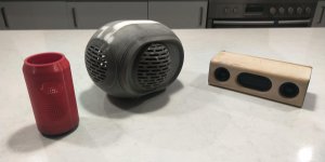
The above is just one 3inch and it has 2 3.5 inch PR's on the sides
I liked the idea of that devalent phantom and thought I'll have a crack and get rid of some of my spare parts. Paint to paint, driving me nuts today lol
The above is just one 3inch and it has 2 3.5 inch PR's on the sides
I liked the idea of that devalent phantom and thought I'll have a crack and get rid of some of my spare parts. Paint to paint, driving me nuts today lol
If you haven't bought it already, the Silent Board is a worthwhile upgrade, as well as rendering the fans as the loudest part of the printer, it eliminates salmon skin (though I can't see any in your prints). My Ender is used for most of my jobs because it's so much easier to set up quickly but, for things like this, I go with the CR-10S Pro because you can throw so much on the build plate (though its BLTouch is much slower than manually running a feeler gauge under the Ender).
I'm rather averse to painting but, when I've done scenery for tabletop gaming, the recipients reported Tamiya spray primer provided the best surface to paint onto.
I'm rather averse to painting but, when I've done scenery for tabletop gaming, the recipients reported Tamiya spray primer provided the best surface to paint onto.
Yeah only had this thing since Feb, been learning a bit, was watching a few YouTube videos on the board upgrade, for me it's a toss up between a new board or if I just upgrade the machine and though a bigger nozzle on the E3
I decided to paint this one as half body print was 22 hours and I paused it and it always tends to just cut through somewhere after resuming and stuffed my two halves, so had to use filler and super glue
I decided to paint this one as half body print was 22 hours and I paused it and it always tends to just cut through somewhere after resuming and stuffed my two halves, so had to use filler and super glue
Pausing on a printer with a single Z screw is usually a roll of the dice. It's funny that you mention bigger nozzles, my strategy is just to accept long print times (each enclosure took 4 days to print).
Yeah I thought as my larger prints didn't really have any major detail, maybe a 0.6 or 0.8mm nozzle would save some time. That entire phantom clone was probably 70hours in total, so a little bit less than those enclosures, but a few weeks the time I scheduled them for my work from home days. I really don't want to let it run over night, heard too many horror stories online about catching on fire and it's put me off a little. Otherwise I would have done the main body in one hit, in lieu of two
You can check whether you have thermal runaway enabled by carefully removing the thermistor and heating the hot end. It should flash an error after a few minutes. With the Ender 3s, the main culprit with early models was a poorly QCd power connector (the yellow one from the PSU). If that's not getting hot after an hour of printing, you're probably safe on that front. If you had a bad one, it would likely have discoloured by now from heating up.
- Home
- Loudspeakers
- Full Range
- Newb TL questions