Good afternoon,
I'm really terrible at making things by hand (dyspraxia) but now I have some experience with 3D printing, I'd like to take a crack at making a transmission line speaker. To keep things simple, I plan to use a single Tectonic TEBM65C20F-8 driver in each one and design it so that it bolts together with no finishing required beyond some soldering.
I've been reading up on transmission line design and used the mh-audio calculator but I had a couple of questions that Google and searching this forum couldn't answer before I proceed to the design phase:
Also, if anyone is working on a project of their own and would like some components 3D printing, I'd be happy to help.
I'm really terrible at making things by hand (dyspraxia) but now I have some experience with 3D printing, I'd like to take a crack at making a transmission line speaker. To keep things simple, I plan to use a single Tectonic TEBM65C20F-8 driver in each one and design it so that it bolts together with no finishing required beyond some soldering.
I've been reading up on transmission line design and used the mh-audio calculator but I had a couple of questions that Google and searching this forum couldn't answer before I proceed to the design phase:
- Is the only factor in the profile of the line its surface area? I was planning to use a circular profile and work out its diameter by taking the mh-audio values for width, turning them into surface areas and then working back to an equivalent circle diameter. If a circle is a poor choice, is there an optimum aspect ratio?
- Is there a good starting point for the placement of damping material on the line? I'm aware that it benefits from experimentation but ask because in the diagrams, it seems to cover the half of the line 'furthest' from the driver.
- Because I'm using FDM, I can vary the density of the walls, would a solid wall between each section of the line (where it doubles back on itself) be better or would a double wall with a filling between reduce transmission of sound through the walls? I can make the filling between them a 3D structure similar to rigid open cell foam at a larger scale.
- I was planning to flare open end of the line slightly at its end, should my line length be calculated to the start of the flare, the end of it or somewhere in between? Alternatively, is this a terrible idea entirely
Also, if anyone is working on a project of their own and would like some components 3D printing, I'd be happy to help.
1/ the surface are aof the driver has no impact on the design. The MH-audio calculator will not give you an optimum TL design.
A TL , like any other box needs to be properly modeled.
My 1st question is, how big is your printer capable of printing. or a proper TL i expect you would have to print it in pieces and glue them together to make the box.
dave
A TL , like any other box needs to be properly modeled.
My 1st question is, how big is your printer capable of printing. or a proper TL i expect you would have to print it in pieces and glue them together to make the box.
dave
Hi Dave,
Thank you for your reply. by surface area, I meant of the profile of the 'tube' that makes up the TL (for example, if a 10x2cm profile were recommended by MH-audio, would a 5cm dia. circle do the same job?). My largest printers can print objects 30x30x40cm and I can glue together or even solvent weld some materials with design features that make the parts self-aligning.
Thank you for your reply. by surface area, I meant of the profile of the 'tube' that makes up the TL (for example, if a 10x2cm profile were recommended by MH-audio, would a 5cm dia. circle do the same job?). My largest printers can print objects 30x30x40cm and I can glue together or even solvent weld some materials with design features that make the parts self-aligning.
Yes, the cross-section of a TL doen’t really care what shape it is (within limits).
But Sd, used as an input in the mh-audio calculator, automatically excludes it from serious consideration. That is the CLassic method of TL design, the huge shortcomings of which have been shown by modern modelers.
dave
But Sd, used as an input in the mh-audio calculator, automatically excludes it from serious consideration. That is the CLassic method of TL design, the huge shortcomings of which have been shown by modern modelers.
dave
Thank you very much for clearing up a misconception on my part. I'll still give it a go, given that the drivers were cheap and I've already ordered them but will temper my expectations.
The best reading for the design of TL is the three part article by Augspurger in Speaker Builder magazine Issue 2,3 and 4 of 2000.
The title of the article is "Transmission Lines Updated".
The title of the article is "Transmission Lines Updated".
The Augspurger articles are required reading but keep in mind that once he did this he did not refine or explore it further. Martin King goes much further with his work.
Quarter Wavelength Loudspeaker Design
dave
Quarter Wavelength Loudspeaker Design
dave
Thank you very much for those links. It feel like I'll need some holiday time just to digest them all.
2 immediate concerns. You are not taking advantage of a driver offset, which can be used to kill th e1st unwanted line harmonic, reduce the amount of stuffing needed and increase bass — althou given the driver and the length of the line this is more of a midTL.
And the smoothed out path is actually counterproductive. It allows too much HF to reach the terminus.
dave
Thank you very much for this. I'd (wrongly) assumed that the reason people were making square-cornered TLs was to simplify construction. Does the driver offset add on to the total TML duct length or is it part of it and is there a fixed ratio or is it calculated from the rest of the parameters?
Last edited by a moderator:
Yes, square cornered TLs were due to construction with flat-panel material. You often see angled corner bits to make it closer to what you did. But one of the things that was clearly shown as people dove into the detail was that these are counterproductive. The expansion at a bend acts as a LP filter, helping to keep undesirable HF from the terminus.
dave
dave
Does the driver offset add on to the total TML duct length or is it part of it and is there a fixed ratio or is it calculated from the rest of the parameters?
No, fixed ratio, i.e. at a pipe's odd harmonics: Z = ~ 0.217, 0.349, 0.424.
Due to the driver's high Qts, recommend an Alpha TL alignment [Fp = Fs/Qts'] with 0.349 offset: http://diyaudioprojects.com/Technical/Papers/Alpha-Transmission-Lines.pdf
Qts' = Qts + any added series resistance [Rs]: HiFi Loudspeaker Design
If you want to put the driver on the end, it basically means that more stuffing will be required to smooth out its response with the trade-off of less bass.
GM
My opinion is that after reading Augspurger artcles (and also Martin King articles), the next step should be to install the "Hornresp" software and start to design a simple TL, although some time will be needed to learn the software.
With programs like Hornresp is very easy to start a design, make whatever changes you want and see the results.
Of course, finally you will need to build the TL to measure and listen to the real thing.
regards
George
With programs like Hornresp is very easy to start a design, make whatever changes you want and see the results.
Of course, finally you will need to build the TL to measure and listen to the real thing.
regards
George
Thank you, George. I did have a play with hornresp to try and figure out the answer to my question on driver offset but I'll definitely read up before using it in anger.
Sorry for being a bit thick, might I ask for a direct answer on whether the offset adds to the length of the duct reccomended by MH audio or if it is part of that total length? i.e. if it reccomend a 60cm duct length, do I move the driver 34.9% down the duct from the end or do I add another 21cm?
Sorry for being a bit thick, might I ask for a direct answer on whether the offset adds to the length of the duct reccomended by MH audio or if it is part of that total length? i.e. if it reccomend a 60cm duct length, do I move the driver 34.9% down the duct from the end or do I add another 21cm?
If the recommended length of the duct is 60 cm, the speaker should be 21 cm from the beginning and 39 cm from the end of the duct.
regards
George
regards
George
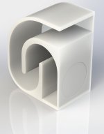
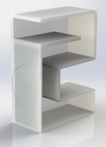
I spent last evening reading up and this evening trying to puzzle out how to offset the driver and still have the port forward firing while also trying to fit the whole mess within the build volume of the printer as well as not have the driver firing on a corner but it's starting to come together. It still needs fitting out, reflector plates adding and wall thicknesses setting. I'll also probably add a truss of some sorts between the two free sections. Thank you again for all the help.
Attachments
HDH,
Have you considered a ported (i.e MLTL) instead of a conventional TL? Adding a reduced area port (like a bass reflex) reduces the overall length required for a given tuning frequency. It seems like that might help you fit the enclosure into the build area easier.
The MLTL configuration also spreads and attenuates (somewhat) the peaks and valleys in SPL characteristic of a TL, without any disadvantage as far as I am aware.
I haven't used Hornsrep myself so I'm not sure if it will model an MLTL, but you can model an MLTL with LATL (Leonard Audio TL) which still seems to be available here:
Transmission Line Download - Modelling software for Windows
Eric
- Home
- Loudspeakers
- Full Range
- Newb TL questions