I think it could decrease distortion , caused by transformer.
however , now i think that transformer changes phase and this type of feedback would not work correctly ...
Am i correct ?
Today i have built my first ESL speaker.
It is 0.25x1 m in size , 1.5 mm spaces between stators and diapraghm.
Diapraghm is made from cooking bags(~12 micron thick) , coated with graphite and cleaned with alcohol.
Stators are stell sheets ( 1mm thick , 5mm holes , 62% open area).
Output transformers are taken from old tube amp.
Resonant frequency is somewhere around 50 hz.
It sounds normal , but worse than my dynamic speaker system that i built few years ago.I am still not sure what is causing problems - transformers or speaker itself.
Hi,
i think it wouldn't decrease dissortion of the stepup, since the dissortions of an appropriate stepup are about 10 times lower than those of the panel.
Let me comment on your panel:
1. Your resonance is too deep if you are looking for an efficient panel. the compliance is such low, that a high voltage of about 800-1000 Volts only will pull the membran to the stator. If you can open your panel without destruction try to further support your membran by adding silicone dots distributed over its area. Lay the stator with the membran towards an even plane and squezze silicone trough the stator openings. Place the dots on the centerline (bottom to top) in distance of about 4" to each other.
2.The wholes of the stator are too wide (5mm). They should be about 2mm max. for a 1,5mm spacing, but thats just a minor improvement.
3. I guess you didn't rub the graphite really strong into the mebran and thus removed signicant portion by cleaning with alcohol.
4. tube amp stepups typically have a turn ratio of 1:40 to 1:50. Your panel could be driven up to 1:80 without compproomising high frequency response.
5. If your power supply isn't able to pull the membran to the stator it might not deliver the voltage required for full loading. if you added the supports mentioned above your panel should be stable up to 2000 Volts.
6. Your actuual frequence response should look as follows:
Heavy peak at resonance (50 Hz) large dip between 60 and 250 Hz (phase cancellation) and 3db/octave level increase aboove 250 Hz.
The last can be optimized by connecting a parallel network of capacitor and resistor to compensate for the increase. You need to figure it out or better to measure
capaciti
1. Your resonance is too deep if you are looking for an efficient panel. the compliance is such low, that a high voltage of about 800-1000 Volts only will pull the membran to the stator. If you can open your panel without destruction try to further support your membran by adding silicone dots distributed over its area. Lay the stator with the membran towards an even plane and squezze silicone trough the stator openings. Place the dots on the centerline (bottom to top) in distance of about 4" to each other.
Using the silicone dots would answer a construction problem for my future panels.
I want to offset the spacers so they are not in contact with the steel stators to reduce
arcing & capacitance. The problem: How to get the center supports to be the same thickness as outside spacers in a single panel design. ( now solved!)...
If starting fresh would silicon dots on one stator still be ok?
Lucius
Hi,
Thanks for help.
I have completely rebuilt my ESL.
now it consists of 4 cells(10x45 cm each).
Gap between spacers and diapraghm is ~0.75 mm.
The sound is much better now as well as sensitivity.
Lukas.
Thanks for help.
I have completely rebuilt my ESL.
now it consists of 4 cells(10x45 cm each).
Gap between spacers and diapraghm is ~0.75 mm.
The sound is much better now as well as sensitivity.
Lukas.
Hi,
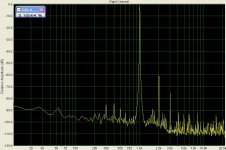
I have measured THD+N of a mains toroid trannie(250W,220/12v).
Don't know if the results are accurate, i used integrated sound card.
If they are , i think it is very good for a mains transformer.
It shows 0.1 % THD at 1 khz and 0.06 % at 5 khz .
Lowest useable frequency seems to be 100 hz.
I used ~20 V input voltage.
Lukas
Attachments
- Status
- Not open for further replies.