This is my first post here on the DIY Audio forums and I am about to build my first Chip Amp.
I have been looking at all of the great designs on this forum as well as others and was wondering what I would do about an enclosure. I have become friends with a guy that just opened a local audio repair shop and he just gave me 3 dead amps with chassis that will be perfect. Plus a lot of good parts in them like transformers, switches, and terminals.
I just ordered the dual mono LM3886 boards from BrianGT. I didn't order the complete kit because I buy components for a living and have access through my suppliers for next to nothing.
Before I get started, I have a couple of questions (actually looking for opinions) on a few things.
1) Stereo vs. dual mono? Any opinions on which design is better or worse?
2) Resistor types? Has anyone used the Dale/Vishay RN series resistors? I have access to almost any value available, and I believe these are better quality than the
ones that are included in the chipamp.com kits. They are metal films with 25 or 50 PPM and 1% tol.
Dual mono is always the best if you have the opportunity.
Ordinary metal film resistors will do if you'll ask me. Temp co 25 or 50 ppm/deg doesn't matter.
If you'll feel better by using other types of resistors, go for it.
Ordinary metal film resistors will do if you'll ask me. Temp co 25 or 50 ppm/deg doesn't matter.
If you'll feel better by using other types of resistors, go for it.
ensure you never run any audio resistors above half their maximum heat dissipation rating.
Preferably keep them below 25% of rating and in the NFB route probably aim even lower.
Preferably keep them below 25% of rating and in the NFB route probably aim even lower.
dual mono
stereo is often cheaper and simplier to do.
dual mono gives the better channel separation and so on(if well done)
greetings..........
stereo is often cheaper and simplier to do.
dual mono gives the better channel separation and so on(if well done)
greetings..........
I decided on dual mono and have the 2 amp boards built and 2 PSU boards built.
I got the 2 Avel 160V 22-0-22 toroids, got the chassis ready and have a few other needed components.
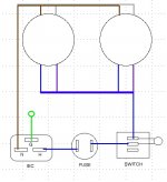
I am ready to tackle the mains wiring, but like most newbies, I want to be sure I got it correct. How does this look?
The switch is already mounted in the case so I was going to use it. It is an SPST illuminated rocker switch. My understanding is the way I show it wired, the switch should work but will not light up. My question is, how to wire it so it lights when on?
I got the 2 Avel 160V 22-0-22 toroids, got the chassis ready and have a few other needed components.
I am ready to tackle the mains wiring, but like most newbies, I want to be sure I got it correct. How does this look?
The switch is already mounted in the case so I was going to use it. It is an SPST illuminated rocker switch. My understanding is the way I show it wired, the switch should work but will not light up. My question is, how to wire it so it lights when on?
Attachments
First, have a look at the switch. Often there is small diagram on, where the right connection is shown. One of the pins is the switch's input. That is, where the wire from the fuse goes. One is common to the switch and light, i. e. output to transformer. And the third is the other leg of the light, which connects to N.
If there is no diagram, you can measure it. Set a DMM to Ohms and measure from pin to pin. Two pins will have either no resistance or nearly 0 Ohms. That is the switch, and if you toggle it, the resistance should jump from 0 to none and back. Then you need to find the matching pair that shows a resistance that is significantly higher than 0 Ohms. That is the light.
Before you do that however, make sure that the switch and the light are rated for your mains voltage. In an increasing number of cases the manufacturers use their main switches on the secondary side, because that makes them cheaper. Then they are not rated for mains voltage and current.
Thanks for the info.
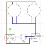
The switch wasn't marked so I figured it out with the DMM. The switch was used in the amp that I am using the case from and it was wired to the primary side in that amp. It's rated 20 amp - 125V / 16 amp - 250V, so it should be fine.
So knowing where the pin for the light is on the switch, the wiring should look something like this, correct? Does the rest of the wiring look correct?
Any suggestions from anyone on doing anything differently?
Attachments
AndrewT said:do you use double pole switches for mains OFF/ON?
This is a single pole switch that was used in an existing amp.
I can see that the switch you have selected is single pole.
I am asking are you allowed to use a single pole switch or must you use a two pole switch for mains ON/OFF.
In the UK we must use two pole in case some eejit wires up the Live and Neutral wrongly.
I would expect the same switching rule to apply to any country that uses non polarised mains outlet sockets.
AndrewT said:In the UK we must use two pole in case some eejit wires up the Live and Neutral wrongly.
Belt and braces, eh? And quite bizarr, when there is an increasing number of devices with no switch at all or with a switch after the secondaries and none before the primaries.
AndrewT said:I would expect the same switching rule to apply to any country that uses non polarised mains outlet sockets.
Germany is one of the countries with non-polarised sockets. Two ways to separate electric and electronic devices from mains are considered safe here (and as far as I know in all IEC member countries). Either use a main switch that cuts all live connections, yet may leave the neutral connected, which is the method of choice for fixed installations. The other method is to use a connector that disconnects all leads from mains. In that case the main switch does not need to interrupt the live wire, because you can always unplug your device from the wall outlet, should the need arise. The main switch is then only there to save energy.
Well, I wired up the mains and I am getting 24VAC at the primaries with the switch in one position and nothing with the switch in the other position. Only problem is the switch stays lit in the on and off position. What did I do wrong?
bookasan said:Well, I wired up the mains and I am getting 24VAC at the primaries with the switch in one position and nothing with the switch in the other position. Only problem is the switch stays lit in the on and off position. What did I do wrong?
You will need to swap the two blue switch wires with each other..
audio1st said:
You will need to swap the two blue switch wires with each other..
Thanks! That was the answer. Actually, that's what I ended up doing just before I read this. I should have logged on earlier as it would have saved me a lot of time trying to figure it out.
The switch is now working like it should.
Is it typical to get 24V out of the secondaries when they are supposed to be 22V?
22 V are the value you get at nominal load. At no load there are always a few volts more. And then there are also voltage fluctuations in the mains.
ask the manufacturer what the regulation value is for the transformer you have.
Look at the label.
Is it rated for 110Vac or 115Vac or 120Vac?
Let's assume you have a 115:22Vac 7% regulation transformer.
Connect 119Vac to the input and expect 119/115 * 22 * 1.07 ~=24.4Vac from the secondaries.
Look at the label.
Is it rated for 110Vac or 115Vac or 120Vac?
Let's assume you have a 115:22Vac 7% regulation transformer.
Connect 119Vac to the input and expect 119/115 * 22 * 1.07 ~=24.4Vac from the secondaries.
pacificblue said:22 V are the value you get at nominal load. At no load there are always a few volts more. And then there are also voltage fluctuations in the mains.
AndrewT said:ask the manufacturer what the regulation value is for the transformer you have.
Look at the label.
Is it rated for 110Vac or 115Vac or 120Vac?
Let's assume you have a 115:22Vac 7% regulation transformer.
Connect 119Vac to the input and expect 119/115 * 22 * 1.07 ~=24.4Vac from the secondaries.
Thanks. Makes perfect sense.
- Status
- Not open for further replies.
- Home
- Amplifiers
- Chip Amps
- new to the forums and new to chip amps