Hi
I would love to learn something about class D amplifiers, but it still seems to be kind of esoteric knowledge. There is still not much "know how" or "how to build" information, at least I didn't find much.
I think I know some basical basics of basic class D amplifier design, probably still not enough to design one myself. I played a little bit with a simulator but I don't trust stupid digital models, life showed that sims cannot predict switching of even small signal bjt's.
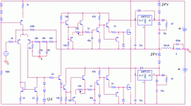
The outcome schematic is in the attachment, I hope you all class D gurus will share a bit of knowledge to help a newbie.
I have several questions:
1. Would it be potentially workable at all?
2. If so, would it be worth building?
3. What are general ways to avoid cross-conduction keeping dead time short and slew rate high? Any suggestions how to improve the schematic below?
4. How to know that class D amp using bootstrap is going to explode on start-up or not?
... and much more...
I am really looking forward to suggestions and discussion.
best regards
Adam
I would love to learn something about class D amplifiers, but it still seems to be kind of esoteric knowledge. There is still not much "know how" or "how to build" information, at least I didn't find much.
I think I know some basical basics of basic class D amplifier design, probably still not enough to design one myself. I played a little bit with a simulator but I don't trust stupid digital models, life showed that sims cannot predict switching of even small signal bjt's.
The outcome schematic is in the attachment, I hope you all class D gurus will share a bit of knowledge to help a newbie.
I have several questions:
1. Would it be potentially workable at all?
2. If so, would it be worth building?
3. What are general ways to avoid cross-conduction keeping dead time short and slew rate high? Any suggestions how to improve the schematic below?
4. How to know that class D amp using bootstrap is going to explode on start-up or not?
... and much more...
I am really looking forward to suggestions and discussion.
best regards
Adam
Attachments
Hi, finally......
Adam, please to try your schematic with simulation. LTSpice (Switchercad) will be good to know your questions.
Because the speed of switch that very high, a discrete class-d needed to be simulated and fine tuned until you have good output result, fastest switching, less cross conduction, etc.
Adam, please to try your schematic with simulation. LTSpice (Switchercad) will be good to know your questions.
Because the speed of switch that very high, a discrete class-d needed to be simulated and fine tuned until you have good output result, fastest switching, less cross conduction, etc.
Because the speed of switch that very high, a discrete class-d needed to be simulated and fine tuned until you have good output result, fastest switching, less cross conduction, etc.
And what if I get satisfactory simulation results? Should I be assured to be able to put schematic to really working circuit? With similar parameters?
regards
Fist, you will know that your circuit works, then you push to the limit during fine tuning.
After that then you make a real test. During real test it may you will find problem, such as heat, cross conduction, so you also make fine tuning on real.
After that then you make a real test. During real test it may you will find problem, such as heat, cross conduction, so you also make fine tuning on real.
Yeah, by analyzing every limitation of the first simulation, you stand a good chance of learning ways of circumventing them one at a time in order to achieve optimal theoretical performance.. which a few exceptions to the real world.
Then compare the first real world prototype performance via test and measurement, to the simulation ideal. Use your powers of obsvervation combined with what you know in theory through research, and possibly collaboration via collegues aand this place, to work out the understanding that will allow the final optimal solution before posting it to us all 🙂
Then compare the first real world prototype performance via test and measurement, to the simulation ideal. Use your powers of obsvervation combined with what you know in theory through research, and possibly collaboration via collegues aand this place, to work out the understanding that will allow the final optimal solution before posting it to us all 🙂
Thank you for responses
I conclude that you cannot tell any possible pitfalls or blatant mistakes from schematic, right?
I conclude that you cannot tell any possible pitfalls or blatant mistakes from schematic, right?
You might want to decrease the value of the inductor a bit. 80uH is pretty high and will have a lot of copper loss unless you want to use heavier gauge wire and end up with a huge inductor.
Thanks Brian
Sounds reasonable.
Do you know any 'thumb' rule to design output filter, like, say: 120% nominal load resistance, 1/3 of switching freq., Butterworth (blind shot here)?
Sounds reasonable.
Do you know any 'thumb' rule to design output filter, like, say: 120% nominal load resistance, 1/3 of switching freq., Butterworth (blind shot here)?
Forget abut simulating discrete switching circuits. Simulation models are intended for linear applications only and you will get weird surprises if you try to build what the simulator tells to be optimum.
What you can simulate with proper software is class D control strategies, but always in a theoretical basis with ideal components.
What you can simulate with proper software is class D control strategies, but always in a theoretical basis with ideal components.
Eva said:Forget abut simulating discrete switching circuits. Simulation models are intended for linear applications only and you will get weird surprises if you try to build what the simulator tells to be optimum.
What you can simulate with proper software is class D control strategies, but always in a theoretical basis with ideal components.
Can't speak for you or anyone else, but I've found a properly posed simulation can be a great tool for all aspects of class d design, both in the frequency and time domains. The art is in knowing what to include and disinclude in the models so the results are a meaningful match to reality and are obtained quickly enough to make simulation a useful iterative design tool. For example, nonlinear Cdg and lead and trace inductance must be properly modeled for useful gate drive design.
Regards -- analogspiceman
darkfenriz said:Thanks Brian
Sounds reasonable.
Do you know any 'thumb' rule to design output filter, like, say: 120% nominal load resistance, 1/3 of switching freq., Butterworth (blind shot here)?
There's no real rule of thumb with class d output filter design. But a good place to start would be a second order Butterworth like you mentioned with a cutoff frequency in the neighborhood of 40-50kHz. You could try 30uH and 0.47uF as a starting point.
Have a look at this pdf from TI for some design tips: http://focus.ti.com/lit/an/sloa119/sloa119.pdf
Concerning output filter:
Inductor value determines the amount of current ripple and how wide is the resulting class AD output power range in which soft resonant switching and little EMI is achieved. That has some similarity to class AB idle current in linear circuits, altough there is inherently no added distortion due to mode transition.
Capacitor value determines how much voltage ripple the inductor current ripple is going to be translated into.
Both capacitor and inductor together determine the resonant frequency and the resonant impedance of the filter. That's only critical for pre-filter feedback designs. Real loudspeaker impedance curve has to be considered, as most tweeters are inductive and their impedance starts to rise above 5Khz, reaching up to 20 ohms at 20Khz (and further rising), thus causing unwanted filter peaking.
- Status
- Not open for further replies.
- Home
- Amplifiers
- Class D
- New to PWM.