yea that's why I want to get an oscope, I'm looking around and through the fourm here. How much can you tell from an analog oscope, is distortion obvious or might you really need a digital one so you could do an fft and find the distortion? I'll post something in that thread when I think about it some more, unfortunately I believe most digital oscopes are 8bit 🙁 as I understand it, 8bits won't measure the difference between a 1% and a .001% amp... So it seems kind of trivial to buy something that inaccurate.
You need an analogue scope of at 20mhz bandwidth. You also need a signal source, preferably a sine/square generator.
The scope will show all the problems of instability such as,
http://www.diyaudio.com/forums/chip...g-audio-integrated-opamps-51.html#post2012430
The scope will show all the problems of instability such as,
http://www.diyaudio.com/forums/chip...g-audio-integrated-opamps-51.html#post2012430
if you can find a cheap 50MHz model all the better.
Look also for a sensitive Vertical scale, 1, or 2, or 5mV/div. 1mV/div is likely to get expensive.
Do not go to digital scope until you know enough to know why a digital scope is actually needed.
Look also for a sensitive Vertical scale, 1, or 2, or 5mV/div. 1mV/div is likely to get expensive.
Do not go to digital scope until you know enough to know why a digital scope is actually needed.
KSA/KSC devices are Fairchild (ex Samsung) devices. Some of them such as the KSA992/KSC1845 are their own versions of the old 2SA992/2SC1845 from NEC.
I'd still say 800mA rated devices for drivers are a bit small. Look at Fairchild KSC2690/KSA1220 for excellent low power drivers. Then of course there's the venerable MJE1503x series from Onsemi.
What are you using for the VAS? At 60V rails, you'll want a TO-126 cased device. Fairchild KSC3503/KSA1381 work well here. Forget using anything TO-92 - with any decent VAS current (around 5-7mA) they will overheat.
I'm beginning to think that I've made an error in choosing the 916's. After making my final circuit design it has the worst oscillation problem out of all 3, seems to be getting worse every time I get more compact. I even tried a simple 2 bjt out stage no ef no cfp, just two transistors. Still oscillates.
I'm using two of them in an EF setup for the vas. They are the 916 complements, ksc 2316 and they are in a...Big to-92 package? I forget what it's called. I think what's happening is that since I'm using the same thing for the vas and the driver I'm getting a natural oscillation between the two stages. That would explain why when I make the circuit layout 'better' it gets worse.
the ksa 992/1845's are only used for the input stage right now.
Last edited:
You need an analogue scope of at 20mhz bandwidth. You also need a signal source, preferably a sine/square generator.
"troll" Ebay for one ... Goldstar oscilloscope OS-7020A - eBay (item 280546973861 end time Aug-17-10 07:02:51 PDT)
This looks exactly like mine. I paid $19usd and 16 for shipping. Best DIY purchase I ever made .. I can now measure things my DMM can't.
OS
TO-92L. They should be OK for VAS duty at 35v though.
The KSA1381/KSC3503 are perfect for VAS use - high voltage, good speed and low Cob. However if you just want to have a play around right now before committing, get some BD139/140 as these work very well at their voltage ratings.
For the output stage - even if you cannot etch a board, you can still use copper clad board. With only a little work it is possible to cut gaps into the board with a knife and scrape channels to form pads. Here's a quick example I knocked up.
Attachments
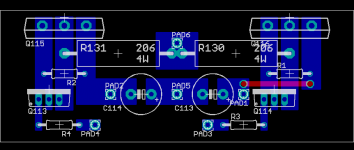
That's awesome, Looks like a CFP stage.
I think I'm gonna find a oscope, probably end up paying about 100$ for one that works off ebay.
I'll order some decent VAS and Driver transistors and try it again. I hope to make a simple version of the amp to test the transistors, Maybe single Trans Vas, Simple Class B output. Dunno yet. Hopefully an OScope will give me some insight as to whats wrong.
Yes it is. TO-220 drivers but you can use TO-126 by just reversing them. The red bit is a wire link.
A scope will really help. I'm finally about to invest in one myself - they are still expensive on ebay here in the UK, havent seen anything worth having under £80!
A scope will really help. I'm finally about to invest in one myself - they are still expensive on ebay here in the UK, havent seen anything worth having under £80!
That's good Jaycee... it might give buzz some ideas.
Also no one has mentioned this but the "official" boards might still be available.
Gareth Conner who is a DIY member is the one to ask at,
The Signal Transfer Company: contact us
Also no one has mentioned this but the "official" boards might still be available.
Gareth Conner who is a DIY member is the one to ask at,
The Signal Transfer Company: contact us
What do you guys think about this one?
Kenwood CS-5165 60MHz Oscilloscope 3 Channels - eBay (item 150388198473 end time Sep-07-10 14:09:48 PDT)
It looks good and there aren't any shady statements about being sold as is or stuff that doesn't work. He shows you a picture of a trace on the screen and es got 6 of them so I'm pretty sure it works, probably from a school lab or something.
Its a little more than I expected to spend but, I don't want to spend 80$ on one that doesn't work right, I'd rather just spend double on one that will last. Looks like it has a 5/2/1mv option too, but its hard to see that dial...
careful
says "analogue" and also says "Sample Rate - Less than 200MSa/s"
This may be a digital scope. Don't touch it if you find out it is a digital scope.
says "analogue" and also says "Sample Rate - Less than 200MSa/s"
This may be a digital scope. Don't touch it if you find out it is a digital scope.
careful
says "analogue" and also says "Sample Rate - Less than 200MSa/s"
This may be a digital scope. Don't touch it if you find out it is a digital scope.
They will mean sweep rate us/div I suspect. It's analogue anyway.
It looks a dual timebase model from the controls... piccys aren't very clear.
That is one of the many Tektronix clones that the japanese did before they werre confident enough to define their ow market.
Analog, delayed sweep, 50ns/cm max plus expand, 3rd (logic level) channel.
If it all works it will be fine for everything you could possibly need in hobby electronics and audio.
Cliff
Analog, delayed sweep, 50ns/cm max plus expand, 3rd (logic level) channel.
If it all works it will be fine for everything you could possibly need in hobby electronics and audio.
Cliff
Got it, yay! Hopefully I'll be able to figure out what I'm doing wrong now. Plus its just cool 🙂 I've needed one before, working on my car but just not had it. Hopefully everything works as described.
What would be a good way to test the circuit as I build it?
I have this idea...
Build input stage - Take one diff. input to audio, run the output (left leg) through a (5k to 20k) voltage divider for a nfb of 5 and then a small 500ohm resistor to ground to turn the current into a voltage measurement.
Do you guys think this would this work to load the input stage for measurement or am I missing something? I would then try to apply this throughout the build, one section at a time. To see each response and how much oscillation I am getting from that additional stage. Hopefully I could figure out how much capacitance I need to be stable and where any problems are.
The amp behaves and must be considered as a "whole".
Anything you "optimise" for just part of the circuit won't be correct when it's all put together.
Having said that I would build the circuit (EF version) and omit the output devices all together. Also have the bias generator shorted out too for zero current in the drivers. Also no zobel network at this point.
Then have a play with the scope and see what everything looks like.
Use something like a 1K as a load resistor and see the effect of crossover distortion.
When you are happy all is correct then think of adding the outputs.
I think we need to add a new thread on here called.... FAIL. I'll post first.
Bottom line, Signal ground was not attached to earth ground. EPIC FAIL. No more needs be said.
Now that I've wasted countless hours simplifying the circuit to almost nothing, it sounds pretty good with only 1 vas transistor (No EF setup) and just output drivers (No EF or CFP) So hopefully when I put it back together it'll all be fine...
Silly Rabbit, Grounds are for kids...
Anyway Thanks for all the help guys. Glad I found out what it was, just took some time away from it to realize what I forgot. I'll post some oscilloscope stuff when I get it all worked out.
- Status
- Not open for further replies.
- Home
- Amplifiers
- Solid State
- New to DIYAudio Help With New Build?