Lm3-v10
.
http://cgi.ebay.com/HiEnd-24-192-DA...=140425021242&ps=63&clkid=5994844694891181043
.
I bought from snow without the transformer just to hear it. You can also buy the same board from Gigaworks. I had my daughter boards upgraded to DIR9001/ CS43122 and it is running direct out through caps, It already sounds better than the AK4395 I have been using even though there is a hiss from the dac chip and I can't use the excellent sounding upsampler board because it adds a whistling noise. It has great potential though so I am going to buy another board with the transformer and with all of the other optional daughter boards to play with until I find the best final solution. I am using 12vdc in for now. It is only powered on the low voltage side of the board since I am not using the opamps. Normal input voltage is labeled as 7 to 10vac and 13v to 15v -0- 13v to 15v. There is good support on the other thread if you want to continue the discussion there.
.
http://www.diyaudio.com/forums/digital-line-level/137976-experience-diy-dac-311.html#post2289248
.
That is the LM3-V10 "Big dac board".Hi Scott, are you running direct out of DAC chip mod on this? which dac chip is it? I have a very similar red DAC board , and mine makes some strange noise when I haven't connected any digital input.
Is one DC supply enough when only running the DAC part of this board? What voltage?
.
http://cgi.ebay.com/HiEnd-24-192-DA...=140425021242&ps=63&clkid=5994844694891181043
.
I bought from snow without the transformer just to hear it. You can also buy the same board from Gigaworks. I had my daughter boards upgraded to DIR9001/ CS43122 and it is running direct out through caps, It already sounds better than the AK4395 I have been using even though there is a hiss from the dac chip and I can't use the excellent sounding upsampler board because it adds a whistling noise. It has great potential though so I am going to buy another board with the transformer and with all of the other optional daughter boards to play with until I find the best final solution. I am using 12vdc in for now. It is only powered on the low voltage side of the board since I am not using the opamps. Normal input voltage is labeled as 7 to 10vac and 13v to 15v -0- 13v to 15v. There is good support on the other thread if you want to continue the discussion there.
.
http://www.diyaudio.com/forums/digital-line-level/137976-experience-diy-dac-311.html#post2289248
.
Attachments
Last edited:
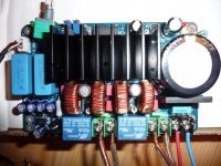
Hifimediy: Do current versions of TK2050 v.1.1B, v.2.0 and T3 (or its PS) include speaker protection against DC? Thanks.
Hi, v2 and T3(with PSU) have DC protection, v1 has only fault(both TC2000 and STA508) protection.Hifimediy: Do current versions of TK2050 v.1.1B, v.2.0 and T3 (or its PS) include speaker protection against DC? Thanks.
Greetings,
Received my v2 kit with Meanwell 27.
Connected everything and started the thing.
All lights seem to be good :
- green on the Meanwell with 23.8 VDC measured.
- green and red lights on the v2 PCB.
I have music ! But only trebble, absolutely no bass, it misses half bandwidth.
Did I miss something ?
For the moment it's running on my second system with small JPW speakers and an old Philips CD player.
All of this is usually working fine with an aura va100 amp, everything worked ok this morning.
Do you have an idea ?
Thank you ! cause I'm close to the end 🙂
Speaker polarity correct yes.
I have veryfied all the inputs from CD player to board : ok.
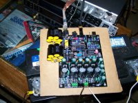
Here is an overview on the v2 PCB : do you see anything wrong ?
And then re-connected speaker + RCA cables to my old amp : everything's working fine 🙁
I have veryfied all the inputs from CD player to board : ok.
Here is an overview on the v2 PCB : do you see anything wrong ?
An externally hosted image should be here but it was not working when we last tested it.
And then re-connected speaker + RCA cables to my old amp : everything's working fine 🙁
Last edited:
Hi, the photo do not show up, could you post again?
Here is again :
An externally hosted image should be here but it was not working when we last tested it.
I also put it in an attached file here.
Regards,
Attachments
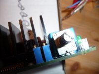
Heya teamacc,I see you twisted the potmeter... Does not seem healthy for the board to me..
I didn't touch anything, potentiometer was like this when received.
Regards,
For you to know : the problem appears on both left and right channels, and the pot turns good, without krrchhkkrrchh.
Regards,
Regards,
It looks like the pot got pushed in the shipment. That could cause this kind of problem.
Can you try to see if you can fix the connection at the pot? Look at the solder joints, and maybe resolder it.
You could also try to connect the signal directly to the big blue caps (on the side of the caps connected to the pot - look on the underside on the pcb, then you see where the pcb traces are going) to see if this could solve the problem.
I can/will try.
2 questions :
- If I avoid the pot, should I introduce 20K resistances to keep input impedance ?
- If I plan to change the pot, should I try stereo 20K pot ? (like ALPS blue or black for example).
But honnestly, I'm not sure it comes from the pot.
I had sound, on both channels, it was symetric, without scratches.
But I'll try.
Thank you,
Regards
Last edited:

dc?
Measure the dc offset between each set of speaker terminals.
.
Measure the dc offset between each set of speaker terminals.
.
Greetings,
Received my v2 kit with Meanwell 27.
Connected everything and started the thing.
All lights seem to be good :
- green on the Meanwell with 23.8 VDC measured.
- green and red lights on the v2 PCB.
I have music ! But only trebble, absolutely no bass, it misses half bandwidth.
Did I miss something ?
For the moment it's running on my second system with small JPW speakers and an old Philips CD player.
All of this is usually working fine with an aura va100 amp, everything worked ok this morning.
Do you have an idea ?
Thank you ! cause I'm close to the end 🙂
OK.
I could turn back the potentiometer to it's place.
Looked under the PCB, apart this scratch, everything's fine.
Offline voltmeter resistance mesures : all ok.
I could turn back the potentiometer to it's place.
Looked under the PCB, apart this scratch, everything's fine.
Offline voltmeter resistance mesures : all ok.
Measure the dc offset between each set of speaker terminals.
.
Measured :
Left : -7.2 mV
Right : -11.2 mV
With volt-meter : red on red, black on black.
Regards,
Last edited:
- Status
- Not open for further replies.
- Home
- Amplifiers
- Class D
- New TK2050 board