Attempt at K-APERTURE in Akabak
Respected Gentlemen of DiyAudio
Hi !
I have attempted to create a K-aperture in Akabak, and i have added this K-aperture to the end of TB-46's Akabak script for his super compact Karlflex attached to post #1188 ..
This K-aperture consists of 6 ducts and 6 radiators (one associated per duct), with the first having small diameter and the last (the mouth) having the largest diameter .....
Perhaps Mr XRK can let me know if this is the correct way to do it?
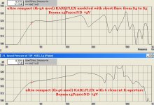
The upper response has changed significantly!! It looks like we are getting some useful midbass and midrange loading from the small front chamber🙂
FB has shifted down by 4hz (from 42hz to 38hz) and therefore output at 35hz has increased ..... Unfortunately we lose a little bit between 45hz and 65hz ......
Roll-off on the bottom end is much smoother .... With the K-aperture this box appears to be well damped, possibly even overdamped ...
Other minor changes to the script (some just for experimental purposes):
-- Disabled S5
-- adjusted driver offset by a small amount
--adjusted "AcouResistance" (damping /stuffing) by a small amount
I attached the Akabak script so folks could review my edits, and let me know if i did anything wrong .... I am still learning to use Akabak so there may be some mistakes ...
Respected Gentlemen of DiyAudio
Hi !
I have attempted to create a K-aperture in Akabak, and i have added this K-aperture to the end of TB-46's Akabak script for his super compact Karlflex attached to post #1188 ..
This K-aperture consists of 6 ducts and 6 radiators (one associated per duct), with the first having small diameter and the last (the mouth) having the largest diameter .....
Perhaps Mr XRK can let me know if this is the correct way to do it?
The upper response has changed significantly!! It looks like we are getting some useful midbass and midrange loading from the small front chamber🙂
FB has shifted down by 4hz (from 42hz to 38hz) and therefore output at 35hz has increased ..... Unfortunately we lose a little bit between 45hz and 65hz ......
Roll-off on the bottom end is much smoother .... With the K-aperture this box appears to be well damped, possibly even overdamped ...
Other minor changes to the script (some just for experimental purposes):
-- Disabled S5
-- adjusted driver offset by a small amount
--adjusted "AcouResistance" (damping /stuffing) by a small amount
I attached the Akabak script so folks could review my edits, and let me know if i did anything wrong .... I am still learning to use Akabak so there may be some mistakes ...
Attachments
Last edited:
Nice work - that is basically how a K aperture is implemented. I have not looked at your script but do you also account for the spatial offset of each radiator? I used rectangular radiators instead of circular ones - not sure if it makes a difference.
must be some kind of code!
Thank you Xrk 🙂
When the radiators all connect to different nodes that are spaced apart does that provide the spacial offset? I can try switching from duct diameter to duct height & width to see if it changes response ...
Here is the code that i used for the K-Aperture:
|---------------------------------------------
| The K-Aperture:
|(in this case the classic K-aperture, series tuned type #1)
|---------------------------------------------
Duct 'P3' Node=12=13
dD=17cm Len=10cm QD/fo=.5
Duct 'P4' Node=13=14
dD=19cm Len=10cm QD/fo=.5
Duct 'P5' Node=14=15
dD=22cm Len=10cm QD/fo=.5
Duct 'P6' Node=15=16
dD=24cm Len=10cm QD/fo=.5
Duct 'P7' Node=16=17
dD=27cm Len=10cm QD/fo=.5
Duct 'P8' Node=17=18
dD=30cm Len=10cm QD/fo=.5
Radiator 'Rad_P3' Def='P3' Node=13
Radiator 'Rad_P4' Def='P4' Node=14
Radiator 'Rad_P5' Def='p5' Node=15
Radiator 'Rad_P6' Def='P6' Node=16
Radiator 'Rad_P7' Def='P7' Node=17
Radiator 'Rad_P8' Def='P8' Node=18
Nice work - that is basically how a K aperture is implemented. I have not looked at your script but do you also account for the spatial offset of each radiator? I used rectangular radiators instead of circular ones - not sure if it makes a difference.
Thank you Xrk 🙂
When the radiators all connect to different nodes that are spaced apart does that provide the spacial offset? I can try switching from duct diameter to duct height & width to see if it changes response ...
Here is the code that i used for the K-Aperture:
|---------------------------------------------
| The K-Aperture:
|(in this case the classic K-aperture, series tuned type #1)
|---------------------------------------------
Duct 'P3' Node=12=13
dD=17cm Len=10cm QD/fo=.5
Duct 'P4' Node=13=14
dD=19cm Len=10cm QD/fo=.5
Duct 'P5' Node=14=15
dD=22cm Len=10cm QD/fo=.5
Duct 'P6' Node=15=16
dD=24cm Len=10cm QD/fo=.5
Duct 'P7' Node=16=17
dD=27cm Len=10cm QD/fo=.5
Duct 'P8' Node=17=18
dD=30cm Len=10cm QD/fo=.5
Radiator 'Rad_P3' Def='P3' Node=13
Radiator 'Rad_P4' Def='P4' Node=14
Radiator 'Rad_P5' Def='p5' Node=15
Radiator 'Rad_P6' Def='P6' Node=16
Radiator 'Rad_P7' Def='P7' Node=17
Radiator 'Rad_P8' Def='P8' Node=18
No, you need to specify x=, y=, z= info below each radiator. The distance refers to the principal axis typically the vent opening centerline. So the middle would be zero and above is plus and below negative y values. Z is into or out of baffle. X is left right lateral offset. Look in manual at example of speaker with two angled tweeters and a woofer. Without this, all radiators are assumed to be spatially emanating from single point. For first order effects it works but not realistic.
AkAbak for Post #1188 Beyma KARLFLEX
Hi Y'all,
This is my second try at this post, if I could only type. 🙂
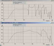
Obviously, xrk971 is correct for final accuracy you need the coordinates for the radiators. You also need to account for all internal volumes, including the volume(s) in the front chamber. I tried using ducts in the front chamber, and attach the radiator ducts (wood thickness) to the nodes between the ducts; I'll attach a sketch, and the AkAbak SPL w/ and w/o stuffing. Looks pretty close to me.
|DATA EXPORTED FROM HORNRESP - RESONANCES NOT MASKED
|COMMENT: KARLFLEX Beyma 15P1200Nd/N_Xmax/mech=9.5/26mm_Paes=1200W_T-TQWT_TRY_small_4seg
|Additional changes based on xrk971's suggestions for simulating the Karlson slot:
|Horn segments 3 and 4 changed to reflect the Karlson slot and front chamber. Feb 28, 2015
|~~~~~~~~~~~~~~~~~~~~~~~~~~~~~~~~~~~~~~~~~~~~~~~~~~~~~~~~~~~~~~~~~~~~~~~~~~~~~~~~~~~~~~~~~~~~~~~~~~~~~~~~
|REQUIRED AKABAK SETTINGS:
|File > Preferences > Physical system constants:
|Sound velocity c = 344m/s
|Medium density rho = 1.205kg/m3
|Sum > Acoustic power:
|Frequency range = 10Hz to 20kHz
|Points = 533
|Input voltage = 75.00V rms
|Integration = 2Pi-sr
|Integration steps = 1 degree ... 1 degree
|Integration method = Cross
|~~~~~~~~~~~~~~~~~~~~~~~~~~~~~~~~~~~~~~~~~~~~~~~~~~~~~~~~~~~~~~~~~~~~~~~~~~~~~~~~~~~~~~~~~~~~~~~~~~~~~~~~
Def_Const |Hornresp Input Parameter Values
{
|Length, area and volume values converted to metres, square metres and cubic metres:
S1 = 198.70e-4; |Horn segment 1 throat area (sq m)
S2 = 551.57e-4; |Horn segment 1 mouth area and horn segment 2 throat area (sq m)
S3 = 321.60e-4; |Horn segment 2 mouth area and horn segment 3 throat area (sq m)
L12 = 75.83e-2; |Horn segment 1 axial length (m)
L23 = 80.36e-2; |Horn segment 2 axial length (m)
SD1 = 314.13e-4; |1st duct segment in front chamber
SD2 = 292.32e-4; |2nd duct segment in front chamber
SD3 = 267.02e-4; |3rd duct segment in front chamber
SD4 = 252.58e-4; |4th duct segment in front chamber
SD5 = 234.85e-4; |5th duct segment in front chamber
SD6 = 213.34e-4; |6th duct segment in front chamber
SD7 = 202.68e-4; |7th duct segment in front chamber
LD1 = 5.44e-2; |front chamber duct segment 1 length
LD2 = 10.48e-2; |front chamber duct segment 2 length
LD3 = 8.03e-2; |front chamber duct segment 3 length
LD4 = 2.45e-2; |front chamber duct segment 4 length
LD5 = 10.48e-2; |front chamber duct segment 5 length
LD6 = 5.24e-2; |front chamber duct segment 6 length
LD7 = 2.54e-2; |front chamber duct segment 7 length
SR1 = 24.91e-4; |1st (top) Karlson slot segment
SR2 = 75.52e-4; |2nd Karlson slot segment
SR3 = 159.98e-4; |3rd Karlson slot segment
SR4 = 284.37e-4; |4th (bottom) Karlson slot segment
LRD1 = 1.19e-4; |Karlson slot baffle thickness
LRD2 = 1.19e-4; |Karlson slot baffle thickness
LRD3 = 1.19e-4; |Karlson slot baffle thickness
LRD4 = 1.19e-4; |Karlson slot baffle thickness
|Parameter Conversions:
Sd = 855.00e-4; |Diaphragm area (sq m)
}
|~~~~~~~~~~~~~~~~~~~~~~~~~~~~~~~~~~~~~~~~~~~~~~~~~~~~~~~~~~~~~~~~~~~~~~~~~~~~~~~~~~~~~~~~~~~~~~~~~~~~~~~~
|Network node numbers for this tapped horn system:
| 0-Voltage-1
| |
| -Driver-------------
| | |
|8-Segment-9-Segment--- front chamber ---Radiators
|~~~~~~~~~~~~~~~~~~~~~~~~~~~~~~~~~~~~~~~~~~~~~~~~~~~~~~~~~~~~~~~~~~~~~~~~~~~~~~~~~~~~~~~~~~~~~~~~~~~~~~~~
Def_Driver 'Driver'
Sd=855.00cm2
Bl=27.52Tm
Cms=8.13E-05m/N
Rms=3.28Ns/m
fs=42.00Hz |Mmd = 162.26g not recognised by AkAbak, fs calculated and used instead
Le=2.70mH
Re=5.20ohm
ExpoLe=1
| by TundraLTD from TH_TinyHorn:
OFF
Filter 'HP1' |Highpass 24dB Butterworth
fo=34Hz vo=1
{b4=1; a4=1; a3=2.613126; a2=3.414214; a1=2.613126; a0=1; }
OFF
Filter 'LP1' |Lowpass 24dB Butterworth
fo=110Hz vo=1
{b0=1; a4=1; a3=2.613126; a2=3.414214; a1=2.613126; a0=1; }
System 'System'
Driver Def='Driver''Driver'
Node=1=0=9=13
Waveguide 'Horn segment 1' Node=8=9 STh={S1} SMo={S2} Len={L12} Conical
AcouResistance 'Stuffing1' Node=8=9 Ra=30e3Pas/m3 | Simulate moderate stuffing
Waveguide 'Horn segment 2' Node=10=9 STh={S3} SMo={S2} Len={L23} Conical
AcouResistance 'Stuffing1' Node=8=9 Ra=30e3Pas/m3 | Simulate moderate stuffing
Duct 'D1' Node=10=11 SD={SD1} Len={LD1} Visc=0
Duct 'D2' Node=11=12 SD={SD2} Len={LD2} Visc=0
Duct 'D3' Node=12=13 SD={SD3} Len={LD3} Visc=0
Duct 'D4' Node=13=14 SD={SD4} Len={LD4} Visc=0
Duct 'D5' Node=14=15 SD={SD5} Len={LD5} Visc=0
Duct 'D6' Node=15=16 SD={SD6} Len={LD6} Visc=0
Duct 'D7' Node=16=17 SD={SD7} Len={LD7} Visc=0
Duct 'RD1' Node=11=18 SD={SR1} Len={LRD1} Visc=0
Duct 'RD2' Node=12=19 SD={SR2} Len={LRD2} Visc=0
Duct 'RD3' Node=14=20 SD={SR3} Len={LRD3} Visc=0
Duct 'RD4' Node=15=21 SD={SR4} Len={LRD4} Visc=0
Radiator 'Horn mouth R1' Node=18 SD={SR1}
Radiator 'Horn mouth R2' Node=19 SD={SR2}
Radiator 'Horn mouth R3' Node=20 SD={SR3}
Radiator 'Horn mouth R4' Node=21 SD={SR4}
***************************************************************
Maybe this will be good enough for a start. I would probably help to break down the first two waveguides into four so the stuffing could be evaluated better.
Regards,
Hi Y'all,
This is my second try at this post, if I could only type. 🙂
Obviously, xrk971 is correct for final accuracy you need the coordinates for the radiators. You also need to account for all internal volumes, including the volume(s) in the front chamber. I tried using ducts in the front chamber, and attach the radiator ducts (wood thickness) to the nodes between the ducts; I'll attach a sketch, and the AkAbak SPL w/ and w/o stuffing. Looks pretty close to me.
|DATA EXPORTED FROM HORNRESP - RESONANCES NOT MASKED
|COMMENT: KARLFLEX Beyma 15P1200Nd/N_Xmax/mech=9.5/26mm_Paes=1200W_T-TQWT_TRY_small_4seg
|Additional changes based on xrk971's suggestions for simulating the Karlson slot:
|Horn segments 3 and 4 changed to reflect the Karlson slot and front chamber. Feb 28, 2015
|~~~~~~~~~~~~~~~~~~~~~~~~~~~~~~~~~~~~~~~~~~~~~~~~~~~~~~~~~~~~~~~~~~~~~~~~~~~~~~~~~~~~~~~~~~~~~~~~~~~~~~~~
|REQUIRED AKABAK SETTINGS:
|File > Preferences > Physical system constants:
|Sound velocity c = 344m/s
|Medium density rho = 1.205kg/m3
|Sum > Acoustic power:
|Frequency range = 10Hz to 20kHz
|Points = 533
|Input voltage = 75.00V rms
|Integration = 2Pi-sr
|Integration steps = 1 degree ... 1 degree
|Integration method = Cross
|~~~~~~~~~~~~~~~~~~~~~~~~~~~~~~~~~~~~~~~~~~~~~~~~~~~~~~~~~~~~~~~~~~~~~~~~~~~~~~~~~~~~~~~~~~~~~~~~~~~~~~~~
Def_Const |Hornresp Input Parameter Values
{
|Length, area and volume values converted to metres, square metres and cubic metres:
S1 = 198.70e-4; |Horn segment 1 throat area (sq m)
S2 = 551.57e-4; |Horn segment 1 mouth area and horn segment 2 throat area (sq m)
S3 = 321.60e-4; |Horn segment 2 mouth area and horn segment 3 throat area (sq m)
L12 = 75.83e-2; |Horn segment 1 axial length (m)
L23 = 80.36e-2; |Horn segment 2 axial length (m)
SD1 = 314.13e-4; |1st duct segment in front chamber
SD2 = 292.32e-4; |2nd duct segment in front chamber
SD3 = 267.02e-4; |3rd duct segment in front chamber
SD4 = 252.58e-4; |4th duct segment in front chamber
SD5 = 234.85e-4; |5th duct segment in front chamber
SD6 = 213.34e-4; |6th duct segment in front chamber
SD7 = 202.68e-4; |7th duct segment in front chamber
LD1 = 5.44e-2; |front chamber duct segment 1 length
LD2 = 10.48e-2; |front chamber duct segment 2 length
LD3 = 8.03e-2; |front chamber duct segment 3 length
LD4 = 2.45e-2; |front chamber duct segment 4 length
LD5 = 10.48e-2; |front chamber duct segment 5 length
LD6 = 5.24e-2; |front chamber duct segment 6 length
LD7 = 2.54e-2; |front chamber duct segment 7 length
SR1 = 24.91e-4; |1st (top) Karlson slot segment
SR2 = 75.52e-4; |2nd Karlson slot segment
SR3 = 159.98e-4; |3rd Karlson slot segment
SR4 = 284.37e-4; |4th (bottom) Karlson slot segment
LRD1 = 1.19e-4; |Karlson slot baffle thickness
LRD2 = 1.19e-4; |Karlson slot baffle thickness
LRD3 = 1.19e-4; |Karlson slot baffle thickness
LRD4 = 1.19e-4; |Karlson slot baffle thickness
|Parameter Conversions:
Sd = 855.00e-4; |Diaphragm area (sq m)
}
|~~~~~~~~~~~~~~~~~~~~~~~~~~~~~~~~~~~~~~~~~~~~~~~~~~~~~~~~~~~~~~~~~~~~~~~~~~~~~~~~~~~~~~~~~~~~~~~~~~~~~~~~
|Network node numbers for this tapped horn system:
| 0-Voltage-1
| |
| -Driver-------------
| | |
|8-Segment-9-Segment--- front chamber ---Radiators
|~~~~~~~~~~~~~~~~~~~~~~~~~~~~~~~~~~~~~~~~~~~~~~~~~~~~~~~~~~~~~~~~~~~~~~~~~~~~~~~~~~~~~~~~~~~~~~~~~~~~~~~~
Def_Driver 'Driver'
Sd=855.00cm2
Bl=27.52Tm
Cms=8.13E-05m/N
Rms=3.28Ns/m
fs=42.00Hz |Mmd = 162.26g not recognised by AkAbak, fs calculated and used instead
Le=2.70mH
Re=5.20ohm
ExpoLe=1
| by TundraLTD from TH_TinyHorn:
OFF
Filter 'HP1' |Highpass 24dB Butterworth
fo=34Hz vo=1
{b4=1; a4=1; a3=2.613126; a2=3.414214; a1=2.613126; a0=1; }
OFF
Filter 'LP1' |Lowpass 24dB Butterworth
fo=110Hz vo=1
{b0=1; a4=1; a3=2.613126; a2=3.414214; a1=2.613126; a0=1; }
System 'System'
Driver Def='Driver''Driver'
Node=1=0=9=13
Waveguide 'Horn segment 1' Node=8=9 STh={S1} SMo={S2} Len={L12} Conical
AcouResistance 'Stuffing1' Node=8=9 Ra=30e3Pas/m3 | Simulate moderate stuffing
Waveguide 'Horn segment 2' Node=10=9 STh={S3} SMo={S2} Len={L23} Conical
AcouResistance 'Stuffing1' Node=8=9 Ra=30e3Pas/m3 | Simulate moderate stuffing
Duct 'D1' Node=10=11 SD={SD1} Len={LD1} Visc=0
Duct 'D2' Node=11=12 SD={SD2} Len={LD2} Visc=0
Duct 'D3' Node=12=13 SD={SD3} Len={LD3} Visc=0
Duct 'D4' Node=13=14 SD={SD4} Len={LD4} Visc=0
Duct 'D5' Node=14=15 SD={SD5} Len={LD5} Visc=0
Duct 'D6' Node=15=16 SD={SD6} Len={LD6} Visc=0
Duct 'D7' Node=16=17 SD={SD7} Len={LD7} Visc=0
Duct 'RD1' Node=11=18 SD={SR1} Len={LRD1} Visc=0
Duct 'RD2' Node=12=19 SD={SR2} Len={LRD2} Visc=0
Duct 'RD3' Node=14=20 SD={SR3} Len={LRD3} Visc=0
Duct 'RD4' Node=15=21 SD={SR4} Len={LRD4} Visc=0
Radiator 'Horn mouth R1' Node=18 SD={SR1}
Radiator 'Horn mouth R2' Node=19 SD={SR2}
Radiator 'Horn mouth R3' Node=20 SD={SR3}
Radiator 'Horn mouth R4' Node=21 SD={SR4}
***************************************************************
Maybe this will be good enough for a start. I would probably help to break down the first two waveguides into four so the stuffing could be evaluated better.
Regards,
Attachments
Edit for Post #1205
Hi again,
A brief edit of Post #1205:
The second AcouResistance has a wrong node in it. It should be:
Waveguide 'Horn segment 2' Node=10=9 STh={S3} SMo={S2} Len={L23} Conical
AcouResistance 'Stuffing1' Node=10=9 Ra=30e3Pas/m3 | Simulate moderate stuffing
Regards,
Hi again,
A brief edit of Post #1205:
The second AcouResistance has a wrong node in it. It should be:
Waveguide 'Horn segment 2' Node=10=9 STh={S3} SMo={S2} Len={L23} Conical
AcouResistance 'Stuffing1' Node=10=9 Ra=30e3Pas/m3 | Simulate moderate stuffing
Regards,
TB46 ,
Thank you for posting that script , it is exactly the sort of thing i needed to look at in order to begin to wrap my head around how to create the k-Aperture in Akabak ...
Would the X= Y= Z= coordinates normally be added to this script as XRK described? Is that a final step?
TB46, please let me know if i have incorrectly interpreted anything below:
SD (1 through 7)= The front chamber's CSA defined in 7 parts..Since the baffle is leaning back it gives us the most area at the top and the least area at the bottom right?..
LD (1 through 7) = Length of K-aperture divided into 7 parts, all parts linked in series (end to end)
SR (1 through 4) = CSA of the K-Aperture itself divided into 4 top to bottom parts, and since this is a traditional K-aperture shape we have less area in the slot shaped sections towards the top and more area in the mouth shaped lower sections ...
LRD (1 through 4) = Thickness of the Aperture panel which in our case is unchanging from top to bottom , 1.19cm or .469" or whatever ...
Question: Could nodes 16 and 17 also have radiators? (D7 and the latter node on D6)
coordination
X,
Thank you for the explanation about coordinates... So based upon what you are saying: If i were to simulate a box that is 24" tall and choose to add the code "Y=25cm" (underneath a radiator's code) it would put this particular radiator near the top of the box and vice-versa "y=-25" would place the center of the radiator near the bottom of the cabinet, is this correct?
No, you need to specify x=, y=, z= info below each radiator. The distance refers to the principal axis typically the vent opening centerline. So the middle would be zero and above is plus and below negative y values. Z is into or out of baffle. X is left right lateral offset. Look in manual at example of speaker with two angled tweeters and a woofer. Without this, all radiators are assumed to be spatially emanating from single point. For first order effects it works but not realistic.
X,
Thank you for the explanation about coordinates... So based upon what you are saying: If i were to simulate a box that is 24" tall and choose to add the code "Y=25cm" (underneath a radiator's code) it would put this particular radiator near the top of the box and vice-versa "y=-25" would place the center of the radiator near the bottom of the cabinet, is this correct?
Last edited:
Hi MMJ,
I think your interpretation of my sketch and the script are correct, the LDx are the length of the individual duct section making up the front chamber.
For the purposes of this example I started the front chamber ducts at the point the small end of the Karlson slot starts. If you use a Karlson slot that extends to the bottom of the baffle you can than add another radiator section that is ducted to node 16, Node 17 is terminated inside the box. My example is just that, an example trying to pull the front chamber, the Karlson slot in the baffle and the radiators apart. You can change the size of the slot, the number of radiators, e.g.: xrk971 ended up using 9 radiators.
You could also change the front chamber ducts into waveguides, again the radiator ducts connect to the front chamber at the junction nodes of the front chamber waveguides, and the radiators connect to the outside of the radiator ducts.
I have had little luck using the advanced features of AkAbak. You need one of the experts to help you further. I think I know what xrk971 was refering to in Post #1204: "... Look in manual at example of speaker with two angled tweeters and a woofer..."
It refers to AkAbak main manual "Position of Radiators, P.46-49". Taking that example you should be able to add XYZ coordinates to the radiators.
Regards,
Last edited:
Hi MMJ,
For the purposes of this example I started the front chamber ducts at the point the small end of the Karlson slot starts. If you use a Karlson slot that extends to the bottom of the baffle you can than add another radiator section that is ducted to node 16, Node 17 is terminated inside the box.
Ok , gotcha, That makes sense, some apertures go all the way to the bottom of the chamber and some don't , now i know we can make both types depending on how many radiators we choose to use and where we place them 🙂
You could also change the front chamber ducts into waveguides, again the radiator ducts connect to the front chamber at the junction nodes of the front chamber waveguides, and the radiators connect to the outside of the radiator ducts.
I have looked at a number of Akabak scripts now and i am getting the impression that waveguides and ducts can be used interchangeably in many cases , right? (but maybe not all?)
I have now applied the coordinates code to the 6-part aperture script i have been learning with ... It was only necessary to add the centimeter figures to the "Y" and "Y-" in order to put the radiators in the right places (vertically) , the rest of the coordinates were "0" since we are centered in terms of left/right...... The results (response, impedance and such) do change a very small amount
 , but it is subtle so i can see that adding radiator coordinates would probably be a final touch after everything else is worked out with this sort of design ......
Last edited:
Ducts and wavefuides are different in that ducts are constant cross sectional area and waveguides can expand or contract (via reversed nodes) and can assume an expansion profile that is conical, exponential, or catenary (variable k). You can also have damping in waveguides via AcouResistance but I am not sure if ducts can do that.
Yes, but at the fundamental level, does viscosity behave the same as pressure drop through fine mesh fibers which is what AcouResistance simulates?
To first order, scaling viscosity may have the same phenomenological effect, but viscosity force is proportional to velocity gradients, so if the flow were to pass through a narrow channel, the viscosity will have a larger effect than damping via non-adiabatic pressure losses.
To first order, scaling viscosity may have the same phenomenological effect, but viscosity force is proportional to velocity gradients, so if the flow were to pass through a narrow channel, the viscosity will have a larger effect than damping via non-adiabatic pressure losses.
Hi xrk971,
Geitmans used ducts throughout his simulation of the TH-Spud, and it seemed to work. http://www.diyaudio.com/forums/subw...ped-horn-th-spud.html?perpage=25&pagenumber=1
I don't have any further experience w/ this subject.
Using AcouResistance does not look straight forward to me either, when I set the original S1 to S3 waveguide sections in the Beyma KARLFLEX to Ra=1e3Pas/m3 I seem to get much more damping than at Ra=100. There seems to be a lot I don't understand about that aspect of AkAbak.
Regards,
Stranger in A Strange Land
I wondered why the waveguide nodes would be reversed (in confuzzling fashion) in some parts of some scripts ... Now i know 🙂
So reversed nodes= Taper or Expansion, and consecutive nodes on a waveguide= constant cross sectional area?
Or is it that Reverse nodes= taper and consecutive nodes= expansion?
I apologize for all of the questions but Akabak is a whole new world for me ............. I am coming up with an interesting script though that i think you guys will like because it is a unique hybrid alignment .... I should be able to post it in the next few days ... It is for these PA-310 drivers and it is a Karlflex, but modified with an extra chamber ....
Ducts and waveguides are different in that ducts are constant cross sectional area and waveguides can expand or contract (via reversed nodes)
I wondered why the waveguide nodes would be reversed (in confuzzling fashion) in some parts of some scripts ... Now i know 🙂
So reversed nodes= Taper or Expansion, and consecutive nodes on a waveguide= constant cross sectional area?
Or is it that Reverse nodes= taper and consecutive nodes= expansion?
I apologize for all of the questions but Akabak is a whole new world for me ............. I am coming up with an interesting script though that i think you guys will like because it is a unique hybrid alignment .... I should be able to post it in the next few days ... It is for these PA-310 drivers and it is a Karlflex, but modified with an extra chamber ....
AkAbak for Dummies 😉 - AVS | Home Theater Discussions And Reviews
That tutorial got me up and running in about 2 hours. Within the first hour I was able to read scripts and draw a schematic of what I was reading, within the second hour I was writing scripts. Although I can write from scratch I do prefer to start with Hornresp and export the file and add to it in Akabak.
That tutorial is a fantastic resource that goes over all the basics. Unfortunately it doesn't go into the advanced features.
Hi xrk971,
Using AcouResistance does not look straight forward to me either, when I set the original S1 to S3 waveguide sections in the Beyma KARLFLEX to Ra=1e3Pas/m3 I seem to get much more damping than at Ra=100. There seems to be a lot I don't understand about that aspect of AkAbak.
Regards,
Just experimenting with the AcouResistance and VISC values i can seemingly emulate the effects that HR's Loudspeaker Wizard "filling" feature gives me .... Still not sure what stuffing densities the VISC figures correlate to though .... For Acouresistance Xrk gave us a 5000- 7500 Pa/m^3 range for typical polyfil in post #1173
So would 5000 be written as RA=5e3Pas/m3 or RA=5000e3Pas/m3 ? or something different?
AkAbak for Dummies 😉 - AVS | Home Theater Discussions And Reviews
That tutorial got me up and running in about 2 hours. Within the first hour I was able to read scripts and draw a schematic of what I was reading, within the second hour I was writing scripts. Although I can write from scratch I do prefer to start with Hornresp and export the file and add to it in Akabak.
That tutorial is a fantastic resource that goes over all the basics. Unfortunately it doesn't go into the advanced features.
Alright , i will check that out right now 🙂
Hi MMJ,
Post *1217: "...would 5000 be written as RA=5e3Pas/m3 or RA=5000e3Pas/m3..."
5e3 = 5000
So it would be 5e3Pas/m3 or 5000Pas/m3.
Regards,
Post *1217: "...would 5000 be written as RA=5e3Pas/m3 or RA=5000e3Pas/m3..."
5e3 = 5000
So it would be 5e3Pas/m3 or 5000Pas/m3.
Regards,
Last edited:
Hi MMJ,
Post *1217: "...would 5000 be written as RA=5e3Pas/m3 or RA=5000e3Pas/m3..."
5e3 = 5000
So it would be 5e3Pas/m3 or 5000Pas/m3.
Regards,
Excellent! Thank you Tb46
I think i get it , so then would 5e2 = 500 , and 5e4 would be 50,000 right?
I just did some searching and found that they call it "minification" or exponential notation .... The number after the "e" is the "power of" (or in this case the number of zeroes) .... They use this in Javascript and some other programming languages, but i never knew this because i never did any serious coding ...
Last edited:
- Home
- Loudspeakers
- Subwoofers
- New sub design? Constricted Transflex, simple build (series tuned 6th order)