Been a long time since my last post asking for preamp recommendations.
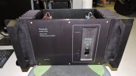
Well I finally landed my first Threshold amp.
It appears to be all stock but Im sure more knowledgeable folks here can tell if Im wrong.
The amp currently works perfectly as far as I can tell. Both ch DC offset is triple digit mv.
Both ch appear to run and idle at a similar reasonable temp. Sorry I didnt take an IR temp of each to be exact yet. But neither seems abnormally hot or cold.
Id really like to treat this fine amp right and give it the proper freshening up.
As Mr Pass himself says, 20-30 yo caps can be replaced. I see no reason to doubt this.
Theres allot of threads about many other threshold amp rebuilds here but I had a hard time finding ones pertaining to the s/200 optical bias itself. I understand much can be applied in general.
Many folks appear to have installed replacement PS caps that double and sometimes triple the original uf value. Im leery of doing any extreme changes like that if it isnt safe for the associated hardware in this amp. I understand many incorporate beefier rectifier, limiting resistors so on. Im no expert as many here are. So I dont dare get crazy incorporating anything of the sort without input from here.
Also Ive seen many thorough rebuilds where the folks replaced all the old carbon resistors throughout. Im not opposed to this. Just wondering if most feel its a worth while effort?
Im all ears to any input, tips, part suggestions.
I own a nice Hakko 300 desolding gun, temp controlled Ersa iron, fluke meter and a basic knowledge of rebuild work. Done some vintage receivers. But Im FAR from the likes of many here. And therefor very much appreciate all the suggestions and input.
Thanks much
Attachments

replace all electrolytics (same value and up to 50% will not do any harm nor demand any changes in associated parts) , Tantal caps if any , recheck torque on output cans mounting hardware , set DC ofset and recheck Iq and that's it
and yes , if any suspicious looking solder joint , just renew it (remove old solder , clean part legs and solder again)
and yes , if any suspicious looking solder joint , just renew it (remove old solder , clean part legs and solder again)
Thanks for the input Zen Mod. Ive read allot of your posts here tried to absorb as much of your info as I could.
Just wondering are you implying even the caps on the input board can be increased by 50% ? Haven't heard that suggestion before.
Im hoping some here will chime in on the proper way to test and set DC offset and idle current on this amp. I know it varies by design in the Threshold line.
And I take it the older Carbon resistors dont bug you?
Thanks again for the input.
Congrats on your 'new' amp. A piece of art in every sense!
I have attached a couple of 'official' documents that explains what you're looking for.
Basically, if the sinks are the same temp on both sides, and somewhere between 42-48 degrees, you're ok.
With regards to electrolytics, change the one on the board with a similar value and quality.
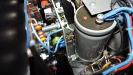
If you replace the PS-caps, go for a similar physical size, so you don't have to drill new holes for the feet. I replaced mine with some Cornell Dubilier at around 35.000uF/80V. They slipped right in.
Resistors... I think Papa wrote somewhere, that the 'carbon'-resistors are actually wirewounds. Anyway, if they look ok. just leave'em.
I have attached a couple of 'official' documents that explains what you're looking for.
Basically, if the sinks are the same temp on both sides, and somewhere between 42-48 degrees, you're ok.
With regards to electrolytics, change the one on the board with a similar value and quality.
If you replace the PS-caps, go for a similar physical size, so you don't have to drill new holes for the feet. I replaced mine with some Cornell Dubilier at around 35.000uF/80V. They slipped right in.
Resistors... I think Papa wrote somewhere, that the 'carbon'-resistors are actually wirewounds. Anyway, if they look ok. just leave'em.
Attachments
Thanks much for the info and docs.
I left the amp running idle for 1 hr 45 min and took thermal temps. Both sides were sitting at 45c. So that would appear to be just fine.
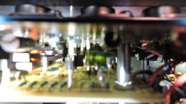
I believe theres 1 poly cap and 1 axial lytic on the driver boards. I assume most feel the poly is fine as is and just replace the one axial? Im open to what you and others suggest.
So one can simply replace the 15000uf caps with 35000uf with no change in rectifier or anything for that matter and all is well? Also did you add any bypass caps with the new PS caps? I know some swear by it.
These appear to be either 2.5" or 3" PS caps in diameter. Ill measure them to be sure.
Also Im pretty sure the resistors in this amp are your typical brown casing carbon ones. They certainly appear to be.
Again thanks for the input and docs. Big help.
I left the amp running idle for 1 hr 45 min and took thermal temps. Both sides were sitting at 45c. So that would appear to be just fine.
I believe theres 1 poly cap and 1 axial lytic on the driver boards. I assume most feel the poly is fine as is and just replace the one axial? Im open to what you and others suggest.
So one can simply replace the 15000uf caps with 35000uf with no change in rectifier or anything for that matter and all is well? Also did you add any bypass caps with the new PS caps? I know some swear by it.
These appear to be either 2.5" or 3" PS caps in diameter. Ill measure them to be sure.
Also Im pretty sure the resistors in this amp are your typical brown casing carbon ones. They certainly appear to be.
Again thanks for the input and docs. Big help.
I have the same S/200 amp, purchased from a buddy a couple years ago (and would love to get another one, and/or a larger model!)
I'm pretty sure it is stock.
Mine also has a mild amount of DC offset, but I don't believe there are adjustment pots on this amp. Aren't new transistors required to reduce/eliminate the offset on this model?
Besides the turn-on thump and low-level noise due to the DC offset, I also have a dead front-panel LED, but I don't have a back-up amp to use while servicing this one.
Please keep this thread alive, as it will push me to take on the deferred maintenance!
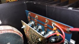
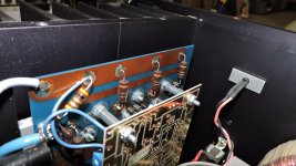
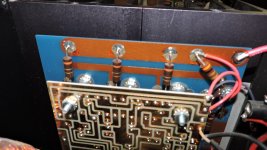
On the resistors that look like carbon comps is the first color band wider than the rest? This signifies WW.
Craig
Craig
Last edited:
Oh wow I had no idea that was the case with the resistors. Yes the 1st band is wider. Im sure Ill be learning allot here.
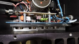
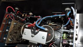
The green axial cap appears to be a 10uf 100v and looks to be non polarized. Without taking the amp apart its hard to see everything. Be great if anyone could verify this. Or if theres a schematic available here for it? Also what folks here would recommend as a good replacement cap?
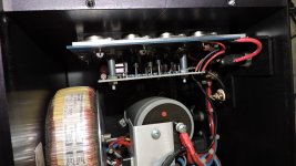
Also the PS caps appear to be 2.5" wide and 5.25" height.
There is also a lone blue trim pot on each board. Im guessing this is the bias pot?
Thanks again to everyone contributing to this post.
And I do hope it helps others in the future.
The green axial cap appears to be a 10uf 100v and looks to be non polarized. Without taking the amp apart its hard to see everything. Be great if anyone could verify this. Or if theres a schematic available here for it? Also what folks here would recommend as a good replacement cap?
Also the PS caps appear to be 2.5" wide and 5.25" height.
There is also a lone blue trim pot on each board. Im guessing this is the bias pot?
Thanks again to everyone contributing to this post.
And I do hope it helps others in the future.
Attachments

On the PS caps.....
I looked at what tedss had up. My understanding is they are a trustworthy vendor.
I found 2 pairs of Cornell caps which dimensional are just right.
One is 30k uf 75v. Another is 42k uf 90v. I dont know if 42k uf is pushing the limits???
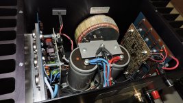
Also the original caps are 80v rating. However the power transformer seems to indicate 40v secondary. I assume that means the amp has a 40v rail? Can the voltage swing up to 80v ? This is clearly beyond my current understanding of amp function.
Thanks again all
I looked at what tedss had up. My understanding is they are a trustworthy vendor.
I found 2 pairs of Cornell caps which dimensional are just right.
One is 30k uf 75v. Another is 42k uf 90v. I dont know if 42k uf is pushing the limits???
Also the original caps are 80v rating. However the power transformer seems to indicate 40v secondary. I assume that means the amp has a 40v rail? Can the voltage swing up to 80v ? This is clearly beyond my current understanding of amp function.
Thanks again all
Do you see the parting line running along the side on those resistors? Carbon comps usually don't have that, another clue to WW.
Craig
Craig
80V rails are usually found in 200WPC amplifiers so your 100W amp will have lower voltage rails.
Craig
Craig
42mF is still in safe area
regarding voltage , what's exact voltage you can measure on big caps , when amp is powered ON?
regarding voltage , what's exact voltage you can measure on big caps , when amp is powered ON?
Thanks again to everyone helping here.
Zen, yeah I knew of measuring the DC voltage at the main PS caps. BTW it measures 54v DC at each cap. Also shows .2v AC at each. Im sure this will sound foolish, but I wasnt sure if this amp could generate more than 54v DC if pushed hard? Im guessing DC voltage remains the same and the amperage simply increases.
So it would seem the stock 80v PS caps are simply there for a wide tolerance with the 54v rails. Built like tank.
On the notion of tantalum caps. Ive read allot of folks replace them with quality lytics or film caps if in the signal path and space allows. Ive also read that depending on how they are used in the circuit, if one subs with a lytic it can cause oscillation.
Anyone care to weigh in on what they would do in replacing the tantalum caps?
Also I believe I read in another thread here that there is only 1 cap in the signal path of the driver board. Not sure if this is the case or not.
Thanks again to all here helping this noob learn.
so , regarding main caps - you can freely use 63Vdc rated ones , that voltage is steady so no worries
Tantalums - they were fashionable in these times , being slightly better than common electrolytics of era , and just later people realized that they're potential popcorns ..... and plain electrolytics became better anyway later
no reason for fear of oscillations - just replace them with decent electrolytics of same or greater capacity , same or greater rated voltage
The 54VDC is unregulated so it all depends on what's coming out of the wall. If your line voltage got to the point where the 80V capacitors were stressed you'd have much greater problems.
Craig
Craig
Once again thanks to all for the info.
I think Im close to being ready to get things under way on the rebuild.
Again I ask if anyone out there has a schematic for the s/200 optical bias amp?
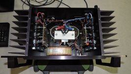
I love how the amp is quite modular in design and taking it apart shouldnt be too hard beyond the wire management.
With that being said, Id still like to hold off on tearing it down until I have all the parts to start the rebuild. Hence my asking about a schematic or if anyone here knows the cap values on the driver board? There seems to be a few tantalum caps on each board.
I have another friend building me a Aleph P 1.7 preamp that should be a great match with this amp.
Again thanks to all.
I think Im close to being ready to get things under way on the rebuild.
Again I ask if anyone out there has a schematic for the s/200 optical bias amp?
I love how the amp is quite modular in design and taking it apart shouldnt be too hard beyond the wire management.
With that being said, Id still like to hold off on tearing it down until I have all the parts to start the rebuild. Hence my asking about a schematic or if anyone here knows the cap values on the driver board? There seems to be a few tantalum caps on each board.
I have another friend building me a Aleph P 1.7 preamp that should be a great match with this amp.
Again thanks to all.
This thread continues to help my understanding of this amp in particular, and amps in general.
Thanks for sharing!
(Now I need to obtain another amp so I can take this one out of service. I'm thinking a pair of mono Pass ACA if I could only free up some time, or PS Audio Stellar if I could only free up some money)
Thanks for sharing!
(Now I need to obtain another amp so I can take this one out of service. I'm thinking a pair of mono Pass ACA if I could only free up some time, or PS Audio Stellar if I could only free up some money)
This makes me wonder if the S/500 I sold to a friend could be bought back. That needed a rebuild too; something that I never got around to doing.
- Status
- Not open for further replies.
- Home
- Amplifiers
- Pass Labs
- New S/200 Optical Bias owner. Welcoming input for a proper refreshing of it.