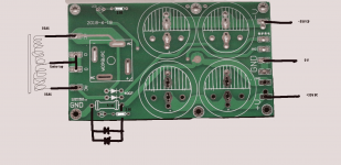
I purchased two of these boards off that auction website. They will serve as the left and right rectifier sections of the power amp I'm building. Dual-Mono design w/ two transformers. From China but not Chinese junk. Nice quality double sided boards. Everything is pretty straightforward except the large connection to ground labeled GND (lower left corner of attached photo). It shows the connection being made through a resistor of unknown value. The other end of the resistor connects to the central ground trace running through the center of the board. These boards came without a schematic.
I cannot find any reference to connecting a power supply to ground (assuming chassis ground in this case) via a resistor. Can anyone shed light or provide an opinion about the use of a resistor between ground and this board? Thanks!

I cannot find any reference to connecting a power supply to ground (assuming chassis ground in this case) via a resistor. Can anyone shed light or provide an opinion about the use of a resistor between ground and this board? Thanks!
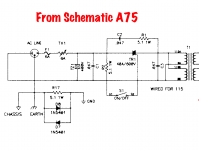
Steve, It's why you should never buy a Chinese board without schematic... but if you search about the A75 Pass Thagard
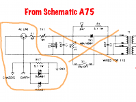
The special resistor is composed of : 1 * 5.1Ω 1Watt resistor and 2* Diodes 1N5401 and please take care of the Connection to the Chassis and to the Common Ground of your design! ( note that the board GND on the right cannot go to the GND ( Chassis ) on the Left.... You will have to modify the Board !
PS: Please a picture of the other side will be useful to help you.
Attachments
Last edited:
Alain, thanks so much!
Here is a photo of the board opposite side. GND is now positioned in the upper left corner. I am not sure how I need to modify the board. Won't all ground connections be to a central STAR ground point? Excuse my lack of expertise. This is my first project.

Here is a photo of the board opposite side. GND is now positioned in the upper left corner. I am not sure how I need to modify the board. Won't all ground connections be to a central STAR ground point? Excuse my lack of expertise. This is my first project.
Last edited:
Well, may I ask in what type of amplifier you want to use these boards ?
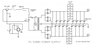
And it works like that:
Center tap to Connection '0' and the 2 transformer outputs wires to the 2 AC Plots
For the leds a resistor of 2.5KΩ is taking about 14mA ( enough for red led's)
and the link to the Chassis is to be modified as indicated in the A75 schema I did already join before.
( You can superimpose the 5.1 Ω resistor with the 2 diodes reversed on the board)
Hope this will help.
Attachments
Hi Alain,
I'm just now seeing you latest reply. In the meantime, I had forged ahead and built the two power supplies. I thought everything through and figured it out, the same as you've just instructed. But thanks so much!
I used a green LED for the positive rail and a red LED for the negative rail. I used an on-line LED calculator which said to use 4.7K resistors but I used 5.1K (same as you recommended) because I didn't have any 4.7K. The 5.1K work fine.
The power supplies provide ~47VDC (+/-). This will be perfect for the amplifier modules. I purchased these modules from an on-line vendor called AMPSLAB. Mike, from Ampslab, assures me that this power supply will work fine with his 60 Watt MOSFET board. The entire project is based on a "junk" Adcom GFA-2535 amplifier. I'm using the case and the two 35V center tap transformers for this project but with new power supplies and amplifiers.
I am wondering if I should use the little circuit you provided (A75 schematic) to connect to ground. Should I use the A75 circuit or just go to STAR ground with a wire jumper instead the A75 diagram. Can you comment on the advantage of the A75 ground configuration?
Lastly, I have read on this website, the advantage of using "Bleeder" resistors to make the power supply "safe" if opened up for service. I kept debating whether of not to use resistors across each of the (4) 10,000UF filter capacitors or just a big one across the positive and negative rails. However now that I've actually built the power supplies, I discovered that the red/green LED power indicators bleed the voltage to a safe level. It took about 7.5 minutes, after the power was disconnected, to reduce voltage from 46.5VDC to 2.5V. Problem solved, I think!
Thanks again (from a newbie) for taking the time to answer my questions and create a schematic for me. I needed to get my hands dirty. Now on to building the amplifier modules and completing the project.
Let me know what you think about using or not using the A75 circuitry.
Hi, Nice to see your PSU works fine, and for the safety of the design the connection to earth and ground works on my A75 since 2004; better take care of this part for security and safety!
Only the circled in orange is needed, and will provide security in case of future problems.
Only the circled in orange is needed, and will provide security in case of future problems.
Attachments
- Home
- Amplifiers
- Power Supplies
- New PSU Bare Board - Opinion on this ground connection (please)