Hi,
I just finished my new preamp with the LME49710NA from National.
I plugged it to my power amp (Atoll AM 100) and listened my favorite songs. It should replace a not so bad passive preamp TCC TC-754 (80$ class).
Remarkable was the clearness of sound without any noise. So much details did I never heard before. But, something was missing. The warmth and the full sound in the lower mids and the basses were thin and dry. I switched to an OPA604. The sound was much "earthier" and darker but there were no details anymore. Not as good as the TC-754. The sound stage wasn't as deep and wide as with the LME.
So, 100 Euro without satisfaction, or? Is there a possibility to pimp up the circuit or would it better to replace the opamp.
The details in the music were great but I am missing the lower frequencies. Would an OPA627 be better? Or which one is a good compromise between details and warmth?
Has anyone a good working circuit for it?
Thanks
Tolu
hi Tolu, if you'd prefer to stick to 8-legged single opamps, I'd suggest ad843 as it would give great bass, a fuller sound, yet dynamic with details. Other good singles that I've used are LM6171 and LM7171 (watch the gain, >2), but these are more neutral sounding than ad843. Carlosfm's ad815 is much better than any of the above, http://www.diyaudio.com/forums/showthread.php?postid=480255#post480255
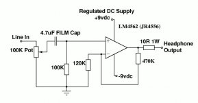
Tolu, have you tried 100n bypass instead of 1uF, and also 100-470n from +v to -v. Btw, the other ends of 49.9k/470p/1k are grounded on the pcb, right? So, the gain = 4x in the preamp. I'd first try a lower gain, say, 2x or just use the LME49710 as a buffer.
trats said:Tolu, have you tried 100n bypass instead of 1uF, and also 100-470n from +v to -v. Btw, the other ends of 49.9k/470p/1k are grounded on the pcb, right? So, the gain = 4x in the preamp. I'd first try a lower gain, say, 2x or just use the LME49710 as a buffer.
I haven't tried 100n instead of 1µF, but what do you mean with 100-470 n from +V to -V?
What do you mean with the other ends of 49.9k/470p/1k are grounded? It is like on the picture. Eingang stands for Input and Ausgang for Output. There is only the Input and the Output Cinch grounded and the rest as on the pic.
The gain is 4x. Do you think gain x1 will warm up the sound?
Regards
Thomas
Oh sorry, I know what you mean with grounding the input section!
I had a look on the original circuit drawing and found that I had forgotten the grounding for Input section and the feedback resistor. But it works although! I am no electrician but a business man so I have sometimes problems of understanding!
What will be the effect of grounding correctly? With an OPA604 there is enough bass. I tried the OPA604 in Class A mode (I took Pin 5 in replacement for Pin 6). It sounded very good but there was very much noise and plops when the cd player stepped from song to song! The missing ground could be the reason, or?
Regards
Thomas
OFF TOPIC
Dear mods,
when can you make an own preamp section in the forum?
I HAVE USED LME49710 AS LINE PREAMPLIFIER WITH GREAT RESULTS.YOUR CIRCUIT IS WRONG.YOU MUST GROUND THE OTHER END OF 49,9K.ALSO BYPASS THE SUPPLY WITH SMALLER CAPS,SAY 100NF.YOU MUST ALSO CONNECT IN SERIES TO OUTPUT A 47-100R RESISTOR TO ISOLATE THE IC FROM CAPACITIVE LOADS.TRY THESE AND...NO PROPLEMS,IT SOUNDS GREAT.
hi,
would like to build this preamp using LME49710HA (they probably would perform even better than NAs). The scheme mentioned is very simple and reminds me the one that is used in Grado RA1 headphone amp. However I have still few questions to clarify, maybe someone could help
1. Input section. So it should be grounded as on Grado's scheme. What blue alps pot should be used? 20k or 100k?
2. PSU. Would lm317-337 circuit be fine with this preamp? Also what caps should be used to bypass the supply? Now it's 1uf mks, 100uf elko, 10n fkp. Should I add 100n also? Would it be fine to feed the preamp with +-12v?
3. Output
To lower the gain to 2-3x 3k resistor on the scheme above should be less, right?
would like to build this preamp using LME49710HA (they probably would perform even better than NAs). The scheme mentioned is very simple and reminds me the one that is used in Grado RA1 headphone amp. However I have still few questions to clarify, maybe someone could help
1. Input section. So it should be grounded as on Grado's scheme. What blue alps pot should be used? 20k or 100k?
2. PSU. Would lm317-337 circuit be fine with this preamp? Also what caps should be used to bypass the supply? Now it's 1uf mks, 100uf elko, 10n fkp. Should I add 100n also? Would it be fine to feed the preamp with +-12v?
ALSO BYPASS THE SUPPLY WITH SMALLER CAPS,SAY 100NF.
3. Output
What does that mean? 🙂YOU MUST ALSO CONNECT IN SERIES TO OUTPUT A 47-100R RESISTOR TO ISOLATE THE IC FROM CAPACITIVE LOADS.
To lower the gain to 2-3x 3k resistor on the scheme above should be less, right?
Attachments

Instead of 10nf, use 100nf or use both.
LM317/LM337 are not preferred. Instead construct a transistorized shunt regulator. Many can be read about in this forum.
Capacitive loads r difficult to drive. So a series R will always keep the impedance above the value of the R.
Gajanan Phadte
LM317/LM337 are not preferred. Instead construct a transistorized shunt regulator. Many can be read about in this forum.
Capacitive loads r difficult to drive. So a series R will always keep the impedance above the value of the R.
Gajanan Phadte
thank you!
-what about the pot, should I use 100k or need less?
-so I could stay with two R on the output: 47 + 100 R, right? 1w 47R & 100R would be enough or need more?
this is my 1st preamp, sorry for some newbie questions 🙂
-what about the pot, should I use 100k or need less?
-so I could stay with two R on the output: 47 + 100 R, right? 1w 47R & 100R would be enough or need more?
this is my 1st preamp, sorry for some newbie questions 🙂
Zin of the amp is set to 100k.
I recommend that the source impedance feeding this should be less then 100k/20. Many would use 100k/10 and I think everyone agrees that 100k/5 is too high for Rs.
The output impedance of a pot used as a volume control is ~ Rpot/4
your 100k pot will present a source impedance to the amplifier that varies from 0ohms to 25kohms.
That puts Rs higher than 100k/5.
Not suitable !!!
The writing means u can use one resistor ranging from minimum 47 to 100 ohms max.
Gajanan Phadte
Gajanan Phadte
Zin of the amp is set to 100k.
I recommend that the source impedance feeding this should be less then 100k/20. Many would use 100k/10 and I think everyone agrees that 100k/5 is too high for Rs.
The output impedance of a pot used as a volume control is ~ Rpot/4
your 100k pot will present a source impedance to the amplifier that varies from 0ohms to 25kohms.
That puts Rs higher than 100k/5.
Not suitable !!!
as you've said I found that source impedance should normally be no greater than 1/10th (0.1) of the pot's stated resistance (according to the article).
How can I get the source impedance (CD and Dac's)? Tried to get it with a digital tester, got 250k on turned on DAC's RCA and nothing on CD.
So there is no common impedance of a pot used with this preamp, right? It should be calculated bearing in mind the source?
The writing means u can use one resistor ranging from minimum 47 to 100 ohms max.
Gajanan Phadte
thanks, now I got it. I thought that ARTISAND was writing about some set of resistors in preamp's output.
Last edited:
dt,
if you have an Rin = 100k and use the 1:20 ratio as your guide, then the maximum Rs shown by the pot to the amplifier is 5K.
A 20k pot will present an Rs of 5k to the next stage.
Now using the same 1:20 ratio as your guide.
If you select a 20k pot as your volume control, then an Rs< 1k will give a compatible source impedance.
Most decently designed sources will have Rs<1k, but some can >1k6.
BUT!!!!
some sources cannot drive capacitive loads.
You use the actual Rs and determine the maximum capacitance that the source can drive.
That will determine the cable type and length allowed for good signal transfer.
You need to do this between each source and the pre-amp and also from pre-amp to power amplifier.
I can recommend LME49720 in a metal case, it's a bit thicker at the lower end (I used it to replace the opamp in my Marantz PM7200 cause it was to polite) and has warm but detailed middle and high.
Also, the resistors you have in the signal path (and feedback) try carbon composite ones cause they react better to music than metal film ones (in my humble opinion). I recommend TAKMAN carbon
If the 470pF capacitor is ceramic, try silver mica
And for the electrolytics use ELNA RFS Silmic II and bypass it with WIMA MKP10 0,1uF or VISHAY-RODERSTEIN MKP-1837 0,1uF.
You can find most of this at partsconnexion.com
AndrewT,
thanks for explanation! I will test with 20k VR first, then try to figure out optimal pot.
mrVetz,
I have several 10HA's (ha stays for metal), so will use them. And thanks for the caps, I still have some FCs and Elna Tonerex, so probably use them here and in PS!
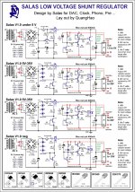
I have spent many hours reading here about shunt regulators and investigating the schemes here. Could anyone advice please, which one to use here? I have attached various +&- regs' versions. Some of them are with LEDs, others don't have zenners (why?!). To my mind they all differ and not so simple to me, previously having experience with LM317-337 only 🙂
thanks for explanation! I will test with 20k VR first, then try to figure out optimal pot.
mrVetz,
I have several 10HA's (ha stays for metal), so will use them. And thanks for the caps, I still have some FCs and Elna Tonerex, so probably use them here and in PS!
I have spent many hours reading here about shunt regulators and investigating the schemes here. Could anyone advice please, which one to use here? I have attached various +&- regs' versions. Some of them are with LEDs, others don't have zenners (why?!). To my mind they all differ and not so simple to me, previously having experience with LM317-337 only 🙂
Attachments

- Status
- Not open for further replies.
- Home
- Amplifiers
- Chip Amps
- New preamp with LME49710