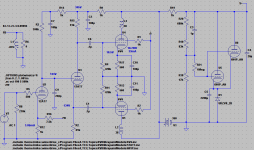
This is what I am working on developing. It is 6LU8 rather than EL84 but it is a similar layout. In this case I am DC coupling VAS to PI by biasing the VAS with plate at approx 1/3 B+. Would there be an advantage in this case of biasing for higher plate voltage and using the voltage divider bias trick for the PI? Does the biasing trick provide any bootstrap effect?

Attachments
That won't work well biasing the split load at that voltage level. See this thread to understand why: http://www.diyaudio.com/forums/tubes-valves/189153-phase-splitter-issue-121.html. Comments 1207 and 1209 of mine pretty well spells it out.
That won't work well biasing the split load at that voltage level. See this thread to understand why: http://www.diyaudio.com/forums/tubes-valves/189153-phase-splitter-issue-121.html. Comments 1207 and 1209 of mine pretty well spells it out.
OK, 1/4 and 3/4, I thought it was supposed to be 1/3 and 2/3. Thanks for the correction.
mike
> what is the purpose in the sort of hybrid coupling scheme (1Meg resistors and .1u cap)?
Straight R-C coupling, gain falls-off to zero at DC. Large pole at the bottom of the audio band.
The 1meg+1Meg divider with cap gives a pole and a zero, an octave apart, and response extends to DC. The 2:1 loss does not give rise to a large phase shift.
In a HIGH-gain design with several stages and large NFB factor, zeroing one pole can make a real difference in subsonic stability.
Here, with a mere 6SL7 (even CCSed) for gain, it is just a fancy. No harm and no great good.
________________
> 1/4 and 3/4
That is the ideal for perfect device and no loading.
Perfect device and significant loading, you may need to be nearer the 1/3 2/3 points.
Real device and significant loading, you may have to go back toward 1/4 3/4.
You will always do well if you take the Resistance Coupled Amplifier table values and put half in each side.
>and no great good.
> 1/4 and 3/4
That is the ideal for perfect device and no loading.
Perfect device and significant loading, you may need to be nearer the 1/3 2/3 points.
Real device and significant loading, you may have to go back toward 1/4 3/4.
You will always do well if you take the Resistance Coupled Amplifier table values and put half in each side.
I don't understand this. The 1/3 2/3 and 1/4 3/4 is not related to the load that the cathodyne drives. That's irrelevant to the issue. The IM distortion is significantly worse in the 1/3 2/3 bias regardless of the loading. It has to do with the uneven symmetry within the cathodyne tube with that type of biasing. For instance with a 360 volt rail voltage and 1/4 3/4 biasing the upper load can move between 180 and 360 volts, ignoring inevitable losses where it won't quite reach those levels. The lower load between 0 and 180 volts. For 1/3 and 2/3 biasing and assuming the same proportional drive signal the upper load will be between 150 and 330 volts and the lower load between 30 and 210 volts. Obviously the upper and lower loads will conflict between 210 volts on the lower load and 150 on the upper load at maximum drive signal that could have been used for the 1/4 and 3/4 max drive signal. In reality there will be significant conflict between the upper and lower way before you get to that. That's what causes the distortion in the higher harmonics. Any transient loud signal can trigger it. It's a bad thing regardless of any other circuit design added to it.
Last edited:
- Status
- Not open for further replies.