The problem as already indicated by me in PM is that discussing designs and design choices in public doesn't work as we can see right now. It may give personal differences, views and even decades of experience a possibly negative appearing exposure to the public eye as well. Besides that one can expect a ton of opinions and side steps. It also does not work to discuss half by PM and half in public. It may work out as it has been proven before but it depends on many factors. When highest quality, high electronic esthetics and simple solutions to everyday annoyances are both a means and a goal chances are that a very nice designed work of art comes to life. It is just a different view on matters, nothing more.
So I wish you and the readers the best of designs and go back to my own designs")
So I wish you and the readers the best of designs and go back to my own designs
Last edited:
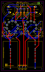
FYI here is the same board using auto routing. I think mine looks nicer.
Find me a relay you want to use on LCSC and I'll integrate it. Right now I'm leaning toward this one HF(Xiamen Hongfa Electroacoustic)|HF(Xiamen Hongfa Electroacoustic) JRC-23F/012-1ZS(555)|Relays|LCSC
Find me a relay you want to use on LCSC and I'll integrate it. Right now I'm leaning toward this one HF(Xiamen Hongfa Electroacoustic)|HF(Xiamen Hongfa Electroacoustic) JRC-23F/012-1ZS(555)|Relays|LCSC
Attachments
My dear kodabmx, you just stated it is NOT about a user friendly preamp and now you want to continue?! What will it be? I am happy to put energy and time in creating a nice design that has many positive features, no more no less. Be it either virtual or not, be it a new design in a new thread.
In this world of cheap and cheerful I would prefer A branded parts and A class design as we have many channels for cheap devices with half of the necessary features omitted already. Even A branded tube devices often lack standard features as known in the world of CD players, DACs and other sources. Simple standard solutions often invented by clever Japanese engineers decades ago.
So ... my design challenge would be to make it a single board versatile stereo tube preamp that may drive any normal semi or tube amplifier, has very low gain, low output Z, has drive capability, has PSU and all integrated, has muting, has volume control, sounds excellent... Completely usable in the only field of DIY audio where mismatching and one offs are standard as people think GAIN is the answer to everything.
What will it be? I am happy to put energy and time in creating a nice design that has many positive features, no more no less. Be it either virtual or not, be it a new design in a new thread.In this world of cheap and cheerful I would prefer A branded parts and A class design as we have many channels for cheap devices with half of the necessary features omitted already. Even A branded tube devices often lack standard features as known in the world of CD players, DACs and other sources. Simple standard solutions often invented by clever Japanese engineers decades ago.
So ... my design challenge would be to make it a single board versatile stereo tube preamp that may drive any normal semi or tube amplifier, has very low gain, low output Z, has drive capability, has PSU and all integrated, has muting, has volume control, sounds excellent... Completely usable in the only field of DIY audio where mismatching and one offs are standard as people think GAIN is the answer to everything.
Last edited:
If you're not interested, I'll discontinue my efforts. I have zero use for the features you asked for, but I don't mind fiddling around with it. It's not like I'm being commissioned for it. I'm just offering a free design for other people to use. As I said, this is a more user friendly, supported line/headphone amplifier designed to be one from the ground up rather than being a simple voltage amplifier for use inside a power amplifier chassis with the power stages: 6N3/6N6 headphone amp using PCB.
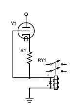
The problem the time delay circuit is I need to modify it to use a transistor I actually have. I already designed a muting circuit that uses a triode strapped 6J1P to drive a relay similar to the design you posted - the difference being the time delay is provided by the warm up of the tube, and the relay is 110VDC - also there are no solid state parts.
The problem the time delay circuit is I need to modify it to use a transistor I actually have. I already designed a muting circuit that uses a triode strapped 6J1P to drive a relay similar to the design you posted - the difference being the time delay is provided by the warm up of the tube, and the relay is 110VDC - also there are no solid state parts.
You also said "So I wish you and the readers the best of designs and go back to my own designs" so I didn't think you were interested in continuing... My error.
I'll play with the delay circuit using parts I have here and see what I can come up with. The circuit is simple enough. When I have a circuit working with parts I have, I'll add them to the PCB.
I'll play with the delay circuit using parts I have here and see what I can come up with. The circuit is simple enough. When I have a circuit working with parts I have, I'll add them to the PCB.
So you do want to design a versatile device? (a question asks for an answer....) Please don't worry about the transistor as almost any NPN transistor will work in the simple circuit. The one used in the schematic is the ECC83 of transistors here.
Yes that was a reaction To this:
Communication... always difficult
Anyway I would not choose semis for muting in the signal path and I would also not choose tubes for a delay circuit. I like to keep matters simple.
You also said "So I wish you and the readers the best of designs and go back to my own designs" so I didn't think you were interested in continuing... My error.
Yes that was a reaction
To this:This isn't meant to be a versatile user friendly preamp though.
Communication... always difficult
Anyway I would not choose semis for muting in the signal path and I would also not choose tubes for a delay circuit. I like to keep matters simple.
Last edited:
My modular amplifier MA-1 is a versatile device - it supports more than 150 types of output tube so far.
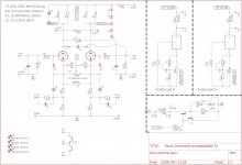
This was not meant to be what it's becoming. That's not an issue, but what I started with and what we have now are drastically different especially in size and complexity. The only reason I included zener shunts was because the power supply voltage can move around in a power amp, and that usually causes motorboating without them. For a line preamp, I'd omit them.
In any case, I've heard "almost any transistor will work" before and it didn't. I have 9014 so I will design around that. I assume you don't want the delay circuit to be SMD?
Since we chose to discuss in public.. I might have a preference for SMD (I have) but knowing the reluctance in this section of diyaudio.com to "new" things like SMD .....
My choice would be SMD, a slightly oversized SMD transistor and a micro relay (really smallest and most affordable) with low hold current for muting. If you like extravaganza also a circuit with red flashing LED during warmup changing to green when not muted is a possibility. For me not a requirement but it maybe adds something.
True and it's up to you as made clear and asked.
My choice would be SMD, a slightly oversized SMD transistor and a micro relay (really smallest and most affordable) with low hold current for muting. If you like extravaganza also a circuit with red flashing LED during warmup changing to green when not muted is a possibility. For me not a requirement but it maybe adds something.
This was not meant to be what it's becoming.
True and it's up to you as made clear and asked.
Last edited:
Personally )) I think a standalone muting board would be much more useful, than integrating one into the PCB. Make it a modular thing that can be expanded into multiple channels for preamp use, power amp use, with small relays for signal level, large relays for output level, etc. Definitely something worthy of it's own project thread. Make it use name brand parts available at the usual mainstream parts supply houses like Mouser, Dig-key, Farnell/Newark, etc.
A modular design can easily be grafted to larger all-in-one PCBs as well for larger more complex designs. A stereo three-way electronic crossover PCB with six outputs, with a muting relay on each output for example.
I like that little relay, I'll see if one of the big guys makes an equivalent. I need to order parts soon.
)) I think a standalone muting board would be much more useful, than integrating one into the PCB. Make it a modular thing that can be expanded into multiple channels for preamp use, power amp use, with small relays for signal level, large relays for output level, etc. Definitely something worthy of it's own project thread. Make it use name brand parts available at the usual mainstream parts supply houses like Mouser, Dig-key, Farnell/Newark, etc.A modular design can easily be grafted to larger all-in-one PCBs as well for larger more complex designs. A stereo three-way electronic crossover PCB with six outputs, with a muting relay on each output for example.
I like that little relay, I'll see if one of the big guys makes an equivalent. I need to order parts soon.
Last edited:
LCSC for the win dude. I design using standard footprints though, just saying why pay 30$ for a CDE cap when I can get one with better datasheet specs for 1$ and change? (Kyet).
I found a smaller relay by Omron, but I don't like the other Omron relays I got so I'll use HF or if I want to spend a lot of money, I'll get Phoenix Contact for 10x the price.
Actually, I have lots of this one - I'll see if there's room for it. HF(Xiamen Hongfa Electroacoustic)|HF(Xiamen Hongfa Electroacoustic) HF115F-012-2HS4|Relays|LCSC
Or for a really small SMD design: HF(Xiamen Hongfa Electroacoustic)|HF(Xiamen Hongfa Electroacoustic) HFD4/5-S|Relays|LCSC
Last edited:
As a long time member of the committee as indicated in my signature a modular approach is far from the ideal we see for mankind as a whole
Anyway the standard telecom relay footprint with added micro relay footprint over it (or SMD version at the other side of the board) makes both types possible. Simple...
Anyway the standard telecom relay footprint with added micro relay footprint over it (or SMD version at the other side of the board) makes both types possible. Simple...
Last edited:
I mean modular as in the layout style Nelson Pass uses in his PCBs, look at the LxMini crossover PCBs for instance- several very basic similar yet different implementations of the same base circuit, all on one PCB. Near copy and paste as needed in the PCB, then optimized for the job at hand. It makes it very easy to lay out, it's functional, and suits well to changes to optimize the overall layout.
Work up a few standalone base PCB designs, and combine as necessary into a larger, less modular all inclusive PCB taylor made for each project application.
Work up a few standalone base PCB designs, and combine as necessary into a larger, less modular all inclusive PCB taylor made for each project application.
It seems we will go astray with this project Multi channel, modular approach, Nelson Pass.... in a section where standardization hardly is known and gain/impedance mismatch is accepted as a kind of quality. Sorry but facts are facts. I think it is wise to make it simple, reliable, functional and stereo all on one board just like kodabmx already does.
If there is an area where a low gain pre/buffer is needed that is usable with almost every source and almost every amplifier then it is this section. Fight the GAIN, brothers!
And sisters of course
Multi channel, modular approach, Nelson Pass.... in a section where standardization hardly is known and gain/impedance mismatch is accepted as a kind of quality. Sorry but facts are facts. I think it is wise to make it simple, reliable, functional and stereo all on one board just like kodabmx already does.If there is an area where a low gain pre/buffer is needed that is usable with almost every source and almost every amplifier then it is this section. Fight the GAIN, brothers!
And sisters of course
Last edited:
A modular approach allows me to change my amp from 6P43P to 12AV5 or EL500 (or so many other types) by changing two circuit boards in ~ 10 minutes though
I agree with Ling though. A separate board for muting would be more universal I think...
Now I'm going to grab an ounce of pot (legal here) and we'll see what else I come up with.
I agree with Ling though. A separate board for muting would be more universal I think...
Now I'm going to grab an ounce of pot (legal here) and we'll see what else I come up with.
Now I'm going to grab an ounce of pot (legal here) and we'll see what else I come up with.
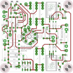
If you must drink and smoke, Smoke first. Heres a board i did with way to much caffeine. Perhaps usefull to get some ideas.
Attachments
I see, then indeed good luck. Sorry for wasting your time.
You aren't. As was said, the circuit can be cut from one board and pasted to another so it can be both.
If you must drink and smoke, Smoke first. Heres a board i did with way to much caffeine. Perhaps usefull to get some ideas.
As a long time smoker and drinker, I have to agree... Learned that lesson about 20 years ago at a friends place. I smoked like I was sober and it wasn't pretty.
Also, Nice artwork.
Ok. I got a version working with the 9014 and the relay that I have, so I'm going to try and lay it out. It's also the first time I used my breadboard and the first time I built something with signal transistors that worked as expected from the first power up. I guess I'm getting better at this.
- Status
- This old topic is closed. If you want to reopen this topic, contact a moderator using the "Report Post" button.
- Home
- Amplifiers
- Tubes / Valves
- NEW PCB: Active loaded triode High Z 9AJ voltage amp.