Leo was an accountant, and by all inference, very much a bean-counter. I don't think he was going to splurge on an extra triode if he absolutely didn't have to. (Though I guess he did splurge when it came to the original Bassman.)if someone didn't mention it, they (Fender tone control circuit) should be driven with a cathode follower
Agreed, I really dislike that 3-knob Fender tone control. It really doesn't work properly, with massive amounts of control interaction (which is a bad thing!) Generations of guitarists have become used to it, however.that midrange control is kinda pointless
-Gnobuddy
Indeed!In a distorting amplifier, the signal is not symmetrical, so it causes a DC offset.
We had a language/miscommunication problem. When you said "up and down", it sounded as though you were describing a bias-wiggle tremolo circuit. Now I understand you were talking about normal bias point shifts due to grid current flow and/or nonlinearity of the output.
There are NO grid stopper resistors shown in the original schematic in post #1. There should be a grid stopper for every triode. They not only help manage high-frequency stability, they can also help control bias shifts during overdrive.
The mid-frequency gain (well inside the -3dB bandwidth) of the amp, is actually set by the transconductance (gm) of the triode and the value of the cathode bypass capacitor.Try adjusting the value of C7 (the cathode bypass for the first tube). Note: the value you need depends on the setting of the cathode resistor
The external cathode resistor does have an effect, it forms a shelving filter along with the valve transconductance and cathode bypass cap. So the external cathode resistance mainly serves to set the size and position of the "shelf" at low frequencies; it's a relatively minor effect, comparatively speaking.
The primary factor that drives the size of the cathode bypass cap is actually the valve's transconductance. This seems to be widely misunderstood.
-Gnobuddy
if someone didn't mention it, they should be driven with a cathode follower
also, that midrange control is kinda pointless, adjusting it simply raises or lowers the overall gain. A lot of guitar amps don't use the cathode follower to drive the tone stack, perhaps they feel it doesn't matter since a guitar is supposedly only good to 10 KHz
Kevin O'Connor (Struth)(The Ultimate Tone Volumes x-xx) has expressed a different opinion many times on this forum.
Since O'Connor seems to have been banned from the forum, would you mind kindly paraphrasing Kevin's comments for us? I'm curious to hear his point of view.Kevin O'Connor (Struth) has expressed a different opinion many times on this forum.
-Gnobuddy
Hi Guys
It is good to see some creativity in preamp design. But...
The original post stated that a modern metal sound is desired and this is most easily attained with four gain stages that each runs free. Free-running stages clip soft and allow a gradual buildup of harmonics. It must be remembered that where feedback-controlled stages are common in hifi and broadcast work, the goal there is to REDUCE distortion not to add it. So, I would suggest you try a more traditional preamp.
The original circuit shows a bootstrapped cathode follower driving the EQ. This is good if you want extremely high clean signals fed to the EQ, but it is contrary to the purpose of the stage in most builds.
As TUT6 details, the CF-driven EQ lacks in tonal dynamics and is a flaw in any amp that incorporates it; EQ is much more dynamic when plate-driven, so wire all four stages for gain.
If you want to retain the CF, place it after the EQ or better yet after the MV so that long cables to a PA can easily be driven.
In an economical high-gain amp with SE output, it is tempting to keep the tube count low. However, this easily cripples tone yet can be done. In this case, a 3+1 architecture is useful with the following layout:
A1 > gain control > A2 > interstage attenuator > A3 > EQ > second-gain pot > A4 > MV > PA
Having the fourth stage to drive the output tube grid assures enough signal is available at that point to do so easily. I've tried many topologies and have generally been disappointed with too few gain stages. In the above layout, the first three stages may need cathode bypass caps to exhibit the gain at high frequencies required for a good metal tone. The fourth stage may or may not need Ck. The interstage attenuator should be adjusted so that no grid-rectification occurs, as usual (see TUT5 for a method for doing this).
As always, every grid should have a grid-stop. It is best not to rely on these for actual frequency shaping and thus their values will be kept low enough to not contribute too much noise.
Variable gain for the first stage is more usual, but as above, the free running stages are preferred especially in a low-tube-count design.
Have fun
This is Struth's post #22 from the thread "Tube preamp design for guitar" on this forum. I have seen him post this opinion many times on this forum.
PS
And the last person to post (#72) on that long thread was...Gnobuddy 🙂
I always appreciate your comments. Thanks
Last edited:
CF tone control
Articles on the Baxandall tone control stated a CF should precede the tone control stage and failure to do so would cause high frequency loss.
My own experience with implementation of filters was confirmatory. I tried to get by without a buffer stage and it did indeed have high frequency loss.
Kevin O'Connor (Struth)(The Ultimate Tone Volumes x-xx) has expressed a different opinion many times on this forum.
Articles on the Baxandall tone control stated a CF should precede the tone control stage and failure to do so would cause high frequency loss.
My own experience with implementation of filters was confirmatory. I tried to get by without a buffer stage and it did indeed have high frequency loss.
Hi Fi high frequency or guitar amp high frequency?
@kwilder: I suggest that - as a student - you read the thread I referenced above. Lots of learning/opinions there 🙂
@kwilder: I suggest that - as a student - you read the thread I referenced above. Lots of learning/opinions there 🙂
Last edited:
Hi Fi high frequency or guitar amp high frequency?
As a guitar is said to go to 10 KHz, and there is only one octave from 10 KHz to 20 KHz, if I, with my aged ears, noticed a distinct loss of high frequency content, I am going to assume that that loss did indeed extend into the range encompassed by a guitar. As guitarists in general seem to dislike "muffled" sound, I should think it would be worth the trouble, especially since it can be implemented with sand and it won't make any difference. a buffer isn't going to impart tonal qualities.
There are those who will point out that a guitar amp speaker typically doesn't get up to 10 KHz, So, maybe it's not worth the effort. FWIW, at least Marshall for one uses the buffer.
your expert also espouses placing the CF AFTER the tone stack which, again, contradicts what Baxendall wrote.
This really gets down to a personal preference and your expert is IMHO, pushing his preference. each sounds different.
Last edited:
Thanks for quoting Struth for us!This is Struth's post #22 from the thread "Tube preamp design for guitar" on this forum.
There are a couple of things he (Struth) said that confuse me. One, he referred to "good metal tone", an oxymoron which makes my eyes water and my mind reel at the mere attempt to understand it. 😀
The second thing Struth said, that I can't make any sense of, is the claim "EQ is much more dynamic when plate-driven". This suggests that the output impedance at the anode ("plate") varies dynamically with signal strength, and does so enough to audibly affect what comes out of the tone control.
Admittedly there is a lot I don't know about valves, but at the moment, I'm not aware of a mechanism that causes this effect in valves. I suppose it's possible that driving a valve to saturation might change the output impedance enough to let an FMV tone control circuit's loading make an audible difference. 😕
If I have time next summer, I might try and test out the "overdrive changes output impedance" hypothesis.I have seen him post this opinion many times on this forum.
Some other points Struth made, I have also seen from other reputable guitar amp designers; for instance, that richer tone is obtained from more valve stages, rather than fewer ones.
(Oddly enough, in my current preamp design, I'm getting better overdriven tone from the two-stage "clean" channel, and worse overdriven tone from the 3-stage "drive" channel. I guess that means I haven't got the best out of the design of the drive channel yet.)
I had already come to my own conclusion that negative feedback (including un-bypassed cathode resistors) was a no-no for an electric guitar amp (except one intended only for jazz and/or electro-acoustic guitar).
That conclusion is fairly easy to come to, if you look closely at what negative feedback actually does: it makes the transition from clean to distorted occur abruptly, rather than progressively. Exactly what I don't want in a guitar amp!
Good gracious, I get around, don't I? 😀And the last person to post (#72) on that long thread was...Gnobuddy 🙂
I actually bought a cheap 12VDC - 220V AC automobile inverter after making that post. I still haven't tried taking it apart and using it to power a valve or two, though.
-Gnobuddy
Jerry, your experience and Struth's comments are not mutually contradictory....I am going to assume that that loss did indeed extend into the range encompassed by a guitar.
If you were enjoying 10kHz content in your guitar tone, I'm going to assume you were listing to fairly "clean" tone. In that case, what little content there is up above 6 kHz sometimes adds a little "shimmer" to the sound, particularly with electro-acoustic guitars.
Struth's comments seem to have been related to an amp designed to produce what he called "good metal tone". Metalheads use so much distortion that their guitars sound like power tools grinding on a rusty tin roof; under those conditions, high frequency treble is intolerably harsh-sounding. So it's not unusual for amps designed for extremely high levels of distortion to also incorporate massive amounts of treble roll-off.
I also have some guitars that really don't put out any high frequency content anywhere near 10 kHz. For instance, one with P-90 pickups. Those big meaty pickup windings have quite a lot of self-inductance, and there just isn't any high treble coming out of that guitar.
It shouldn't, if properly designed. However, Leonidas (or his technician at time the Bassman was being designed) didn't have much of a clue about electronics design.a buffer isn't going to impart tonal qualities.
So he ended up using a cathode resistor that was far too low for the valve in question (a 12AX7). The result was that the cathode follower was actually biased extremely "hot", so "hot" that it could barely generate any positive-going output half-cycles, only negative-going ones.
So Leo's badly-botched cathode follower actually does introduce massive amounts of harmonic distortion! And it lives on to this day in many high-gain guitar amp designs, for precisely this reason - in order to generate lots of distortion without excessive voltage gain coming along for the ride.
Using a CF after the tone stack reduces the loading from the master volume pot, which otherwise reduces the control range of the tone stack, and also - surprise! - causes treble loss.your expert also espouses placing the CF AFTER the tone stack which, again, contradicts what Baxendall wrote.
The "proper" thing to do would therefore be to use a CF both before and after the tone stack, but I doubt any commercial guitar amp builder will want to splash out the cash for that.
Baxandall? A talented designer who gave us a wonderful tone control circuit, but he never envisaged intentional massive distortion, did he? Surely he wasn't thinking about electric guitars when he designed his namesake tone control.
I concur. And, while I don't know Struth, I've read a number of his posts on this forum, and he certainly had strong preferences, which he wasn't shy about sharing. 🙂This really gets down to a personal preference
-Gnobuddy
This particular line is quite wrong, in fact the opposite of what really happens.the CF-driven EQ lacks in tonal dynamics and is a flaw in any amp that incorporates it; EQ is much more dynamic when plate-driven, so wire all four stages for gain.
Passive tone controls present a complex, and quite low (lower than what appears at first sight) load to the previous tube driving them.
On first sight, most casually look at them and think "oh, 250k/1M pots, easy to drive" but the real load is the frequency selective network.
In a typical Fender (blackface) tone control and in a simplified analysis, just considering each branch on its own:

the previous plate "sees" all the time the Bass network: 100k in series with .047uF meaning it sees a 100k load at all guitar frequencies.
Which is also in parallel with 250k above 2500Hz and also *attenuates* such frequencies if driven from a high impedance source.
That alone is a heavy load for a 12AX7 with a 100 k plate resistor, its generator impedance is around 40k (internal impedance of around 60/70k in parallel with 100k load resistor), so that both reduces possible gain big way and makes tone controls quite interactive, since being fed from a relatively high impedance they "fight" for whatever drive is available.
With Bass control set to 0 the .1uF cap gets in parallel with the .047 one, although any effect on load happens outside the guitar band.
Treble control on 0: tone control output is low impedance because audio is taken across the .047uF cap, so bass easily feedsthe next stage.
Treble control on 10: now bass has 250k in series, net effect is that "boosting highs attenuates bass" , a widely known characteristic of Fender amps which in practice is useful to Musicians, and makes the treble control appear as stronger than what it really is.
The "mid" control only makes the notch created by the tone network less deep, a very poor range control but hey, it is what it is, what else can be expected from a single pot with no capacitors associated to it?
It´s noticeable at low settings of treble control , because setting it higher rises "everything" , not just mids; when bass and treble are set high, it becomes very subtle (politically correct way of saying: useless).
In all, a very interactive tone control which is made worse by poor (high internal resistance) drive.
A modern active tone control would be flat with TMB knobs all set to 5 (on a 0-10 scale) , while Fender tone control driven as mentioned above is flat when on 0 - 7 - 0.2 😱

How can anybody call such poor dynamics "dynamic" is beyond my understanding.
Now to the CF driven Fender Tweed/Marshall tone control.
An externally hosted image should be here but it was not working when we last tested it.
Even if it´s basically the same, and network impedances are lower, now previous tube sees even lower network impedance, since bass net resistor is 68k or 33k 😱 and treble cap is 250pF or 470pF , in the latter case meaning that 250k treble pot now loads driving stage above 1400 Hz 😱 ... BUT ... it is driven from a cathode follower which shows WAY lower impedance so it´s WAY less interactive.
The mid control still is as poor as before 🙁
So we can see that the cathode follower IS useful and a game changer ... for good.
That´s why most (>95%) Metal amps use them, with the notable exception of Peavey on 5150 and derivatives ... although they use CF in their regular Metal amps, such as Butcher:

are 95% of Metal amp designers *wrong* ? 😕
Last edited:
Thanks for these responses.
As I said, Struth has made this claim a number of times but without explanation in support.
Yes, I was fishing for a response from those who know more than I. Thanks again.
As I said, Struth has made this claim a number of times but without explanation in support.
Yes, I was fishing for a response from those who know more than I. Thanks again.
Ok, so I added the grid block resistors and it both brought down the preamp gain and stopped the oscillation at high preamp gain. Great suggestion, Thanks! There is alot of good info about the tone stack here, but I need to put that aside till I can meet the specified power and harmonic distortion output required of me for my project.
Right now, the amp is only putting out about 1.2W and is breaking up kind of early. I know, according to the datasheet, that I should be able to get 5.5W out at 12%THD.
http://www.radiostation.ru/tubes/6V6GT-GE.pdf
This presumably means I can get more out of it at higher distortion. I measured the power of my 15W fender superchamp xd (6v6 PP config) and the max I could get out of it was 52W calculated with the RMS voltage across the load ^2 divided by the load resistance (8 ohm). The signal was very distorted at this point.
I should also say, how the test was conducted. I am putting a 300Hz sine wave in and measuring the voltage out across the dummy load (a big 8 ohm power resistor). I am increasing the input voltage till the amp saturates and stops putting out more power. Is this the wrong way to measure power? I get more out of my amp when measured across the speaker (also 8 ohm) but I know you can't trust this, because the speaker is inductive and the impedance changes with freq and changes with the position of the cone. In addition the current and voltage are not in phase.
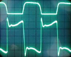
With the sine wave input and my amp cranked, here's what the output looks like, and it isn't what I expected. It doesn't look like the typical clipping tube output, like a sine wave with the tops rounded off and slanting:
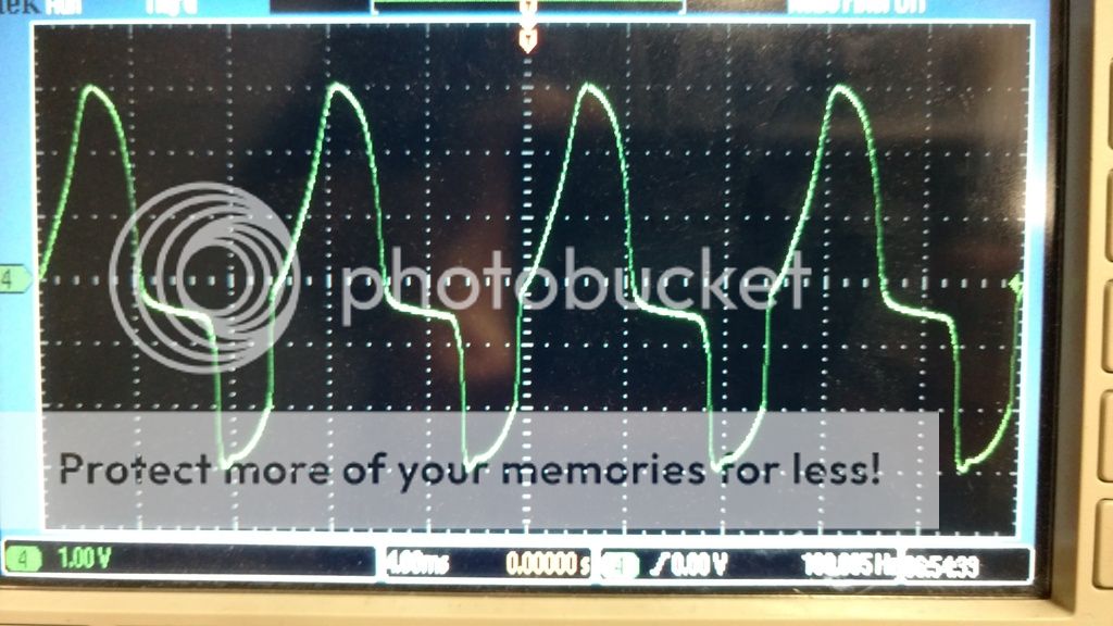
I am not sure if there is some strange phase shift in my circuit causing this.
I believe my power output issue is in the power amp circuit, because lowering the gain of the preamp (with the grid stopper resistors) did not change the power output of the amp.
Here is the power amp circuit. It was designed by my partner on the project, and it looks good to me, but I didn't do the engineering behind it:
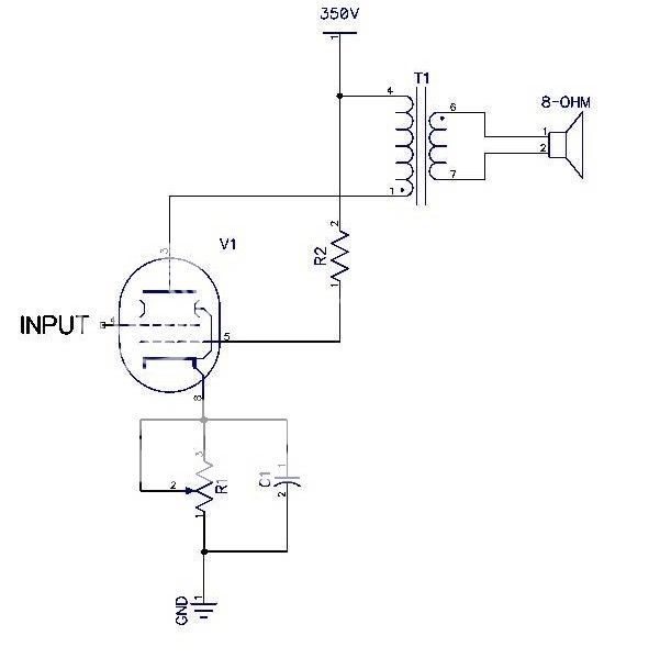
R1 is 460 ohm (this is a pot. the grid is biased at about -14V)
R2 is 43k (this gives screen voltage of 240v, measured)
C1 is 33uF
Transformer primary is about 5k ohm. I verified this in the circuit based on voltage ratios. It is a replica of a fender class A OT from a princeton. (circuit here: http://elektrotanya.com/PREVIEWS/63463243/23432455/fender/fender_princeton-5c2.pdf_1.png
I don't know what is causing this Lack of power. Is it possibly got to do with screen voltage? The cathode bypass? I thought it mostly had to do with B+ voltage and load impedance (the transformer)
For some reason I don't believe the measurement I am getting into the resistive load. It is definitely quieter than my super champ xd (15 W rated but measured 52W!) but not as quiet as I would think being that the output is almost 50 times lower. But then again, my super champ put out more than it's rated power into the dummy load. The amplifier should easily achieve over the power that it is "rated" at, while it is in distortion, I would think. And 6v6 class A amps are usually rated around 5W. For my specs to pass senior project, the power output spec is 5W at any distortion level. There are other specs, but this is the first one to tackle.
Sorry for the book length post and thanks in advance for suggestions
Right now, the amp is only putting out about 1.2W and is breaking up kind of early. I know, according to the datasheet, that I should be able to get 5.5W out at 12%THD.
http://www.radiostation.ru/tubes/6V6GT-GE.pdf
This presumably means I can get more out of it at higher distortion. I measured the power of my 15W fender superchamp xd (6v6 PP config) and the max I could get out of it was 52W calculated with the RMS voltage across the load ^2 divided by the load resistance (8 ohm). The signal was very distorted at this point.
I should also say, how the test was conducted. I am putting a 300Hz sine wave in and measuring the voltage out across the dummy load (a big 8 ohm power resistor). I am increasing the input voltage till the amp saturates and stops putting out more power. Is this the wrong way to measure power? I get more out of my amp when measured across the speaker (also 8 ohm) but I know you can't trust this, because the speaker is inductive and the impedance changes with freq and changes with the position of the cone. In addition the current and voltage are not in phase.
With the sine wave input and my amp cranked, here's what the output looks like, and it isn't what I expected. It doesn't look like the typical clipping tube output, like a sine wave with the tops rounded off and slanting:
I am not sure if there is some strange phase shift in my circuit causing this.
I believe my power output issue is in the power amp circuit, because lowering the gain of the preamp (with the grid stopper resistors) did not change the power output of the amp.
Here is the power amp circuit. It was designed by my partner on the project, and it looks good to me, but I didn't do the engineering behind it:
R1 is 460 ohm (this is a pot. the grid is biased at about -14V)
R2 is 43k (this gives screen voltage of 240v, measured)
C1 is 33uF
Transformer primary is about 5k ohm. I verified this in the circuit based on voltage ratios. It is a replica of a fender class A OT from a princeton. (circuit here: http://elektrotanya.com/PREVIEWS/63463243/23432455/fender/fender_princeton-5c2.pdf_1.png
I don't know what is causing this Lack of power. Is it possibly got to do with screen voltage? The cathode bypass? I thought it mostly had to do with B+ voltage and load impedance (the transformer)
For some reason I don't believe the measurement I am getting into the resistive load. It is definitely quieter than my super champ xd (15 W rated but measured 52W!) but not as quiet as I would think being that the output is almost 50 times lower. But then again, my super champ put out more than it's rated power into the dummy load. The amplifier should easily achieve over the power that it is "rated" at, while it is in distortion, I would think. And 6v6 class A amps are usually rated around 5W. For my specs to pass senior project, the power output spec is 5W at any distortion level. There are other specs, but this is the first one to tackle.
Sorry for the book length post and thanks in advance for suggestions
screen resistor WAY too high
It is customary with the 6V6 to run the screen voltage very close to the plate voltage. Based on research I just did, that high value screen resistor is going to decrease the power.
The 6V6 sounds very good when the screen and plate voltages are close, with screen voltage of course a little bit less. I have noticed as you widen the gap between plate voltage and screen voltage, the sound will get more "dynamic," but you pay for it with what I call "pentode screechiness."
Not having the screen resistor bypassed is going to provide a form of negative feedback. in an appropriately sized screen resistor (1K or below) , this negative generally provides for less distortion, This being a guitar amp, you don't need to worry about that so much. if you are keeping the plate voltage at a reasonable level for the 6V6, why don't you try reducing the screen resistor?
BTW, your schematic shows input at the screen and the screen resistor connected to the grid.
it is helpful to think of the voltage dropping resistor (screen resistor) as part of the power supply, providing a voltage "tap." Obviously, it should be bypassed for voltage stability. THEN, you add in the screen resistor, 100 to 1000 ohms, probably on the low end, and attach directly to the tube socket.
make sure the grid has a high value resistor to ground or common.
it would be helpful to see everything, power supply included. Even selection of rectifier matters in terms of "tone."
Last edited:
Scopes don´t lie [tm]It doesn't look like the typical clipping tube output, like a sine wave with the tops rounded off and slanting:
What you see is the TRUE tube power amp clipping waveform ... one of them at least.
Ever notice that all those nice rounded top waveforms shown in most books and repeated and nauseam all over the Net are DRAWN?😱
And why are they drawn? because it´s as easy to take a picture proving what they claim, as of taking a nice sharp clear picture of Bigfoot, Santa Claus or Mickey Mouse (hint: they are all creations of the Human Fantasy).
Typical Net/Forum/Guru Book example of tube distortion, some compare it to SS distortion:
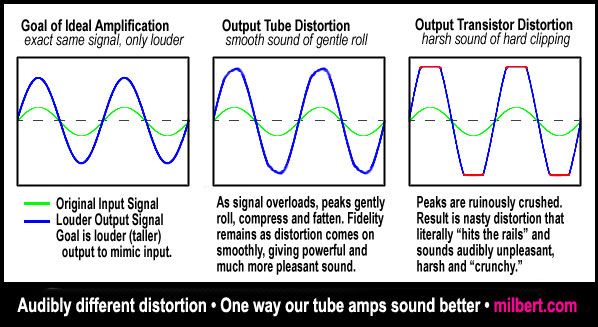
"Soft clipping tubes" vs "hard clipping SS"


more fantasy:

so called"tube clipping"
An externally hosted image should be here but it was not working when we last tested it.
Now some REAL WORLD Scope captures:

a KILLER sounding Marshall 18W, driven full tilt:
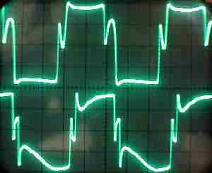
to know whaththese waveforms mean, listen to the 18W Marshall video, it starts clean (sort of, it is a marshall) and the above waveform matches what you hear about video minute 03:00 :
https://youtu.be/E-g1hFZtBPc?t=1m24s
the struth and nothing but the struth
when it comes to guitar amps, it is inevitable that one will encounter many topics which will have two camps firmly staked out. This is true of audiophile tube amps as well, but not to NEARLY the degree I have encountered with guitar amps. So much controversy and so much just MISinformation and DISinformation that I long ago resorted to running my own tests and experiments to get to the bottom of many controversies. Even people with engineering degrees can't agree and/or are just flat out wrong.
THere are two camps with strong opinions, ,CF or no CF
Active tone stack or passive tone stack.
after reading through what the self-proclaimed maestro OPINES, I think I will avoid stepping in piles of Struth. he's wrong enough that i find suspect anything he has to say.Kevin O'Connor (Struth)(The Ultimate Tone Volumes x-xx) has expressed a different opinion many times on this forum.
when it comes to guitar amps, it is inevitable that one will encounter many topics which will have two camps firmly staked out. This is true of audiophile tube amps as well, but not to NEARLY the degree I have encountered with guitar amps. So much controversy and so much just MISinformation and DISinformation that I long ago resorted to running my own tests and experiments to get to the bottom of many controversies. Even people with engineering degrees can't agree and/or are just flat out wrong.
THere are two camps with strong opinions, ,CF or no CF
Active tone stack or passive tone stack.
Run out of image space, here´s more TRUE scope captures:
this is a complex but common case: the bottom push pull tube is almost dead of old age, has such a little cathode emission and voltage gain that it is too feeble to even saturate; the top tube is fresh and easily saturates BUT the very different current capability causes imbalance in the OT core, it is partially saturated and lost inductance, meaning it lost bass (see the upwards slanting top half wave) , a very complex waveform indeed:
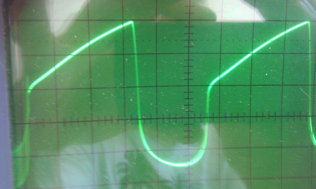
asymmetrical distortion created by (very poor performing) concertina type phase inverters.
Power tubes reproduce this quirky waveform and add their own wild peaky clipping as shown in earlier examples:

to boot the cathode driven tube gets blocking distortion, while the plate driven one does not, this twists even more the output signal.
Overdriven preamp tube, showing input and output signal for comparison:

Well, now you clearly see the differenc between myth and reality.
And that such an easy to disprove myth goes on and on and on all over the place tells me that *many* (most??) who speak about tubes have not done much practical building or experimenting, but rather read a lot of Forums and write what seems to be the consensus or copy each other`s books or pages.
Mind you, I have seen the fancy unreal drawings even in respected manufacturers literature ("M.B." cough cough) who should know better.
An externally hosted image should be here but it was not working when we last tested it.
An externally hosted image should be here but it was not working when we last tested it.
this is a complex but common case: the bottom push pull tube is almost dead of old age, has such a little cathode emission and voltage gain that it is too feeble to even saturate; the top tube is fresh and easily saturates BUT the very different current capability causes imbalance in the OT core, it is partially saturated and lost inductance, meaning it lost bass (see the upwards slanting top half wave) , a very complex waveform indeed:
asymmetrical distortion created by (very poor performing) concertina type phase inverters.
Power tubes reproduce this quirky waveform and add their own wild peaky clipping as shown in earlier examples:
to boot the cathode driven tube gets blocking distortion, while the plate driven one does not, this twists even more the output signal.
Overdriven preamp tube, showing input and output signal for comparison:
Well, now you clearly see the differenc between myth and reality.
And that such an easy to disprove myth goes on and on and on all over the place tells me that *many* (most??) who speak about tubes have not done much practical building or experimenting, but rather read a lot of Forums and write what seems to be the consensus or copy each other`s books or pages.
Mind you, I have seen the fancy unreal drawings even in respected manufacturers literature ("M.B." cough cough) who should know better.
Last edited:
I agree with everything you've said about the awful, awful Fender tone control design. Also everything you said about how heavily the tone control circuit can load a common-cathode 12AX7 stage. And I have serious doubts about Struth's claim.How can anybody call such poor dynamics "dynamic" is beyond my understanding.
However, for now, I am trying to keep an open mind about what he (Struth) said, based on one word he used: "dynamic". This word is frequently mis-used these days, but one of the real (dictionary) meanings of the word is: "relating to the volume of sound produced by an instrument, voice, or recording."
I'm going to make the assumption Struth meant exactly this; that he was saying that the frequency-dependent loss caused by the heavy loading of a Fender tone control circuit would actually change dynamically, as the signal level goes up and down.
If the source impedance of a triode gets lower when it is driven hard into saturation (which at least seems plausible), then the frequency-dependent loading from the tone stack will have less effect when the tube is being driven hard. In effect, you'd have a sort of crude envelope filter effect, with the frequency response changing a little with signal dynamics. If true, it would cause timbre variations with signal dynamics, which is a characteristic of all traditional musical instruments, and also a characteristic of good electric guitar amps.
I'll admit quite frankly that I'm skeptical about all this. It sounds like a lot of the nonsense we frequently hear from "audiophools". But, if I can think of a way to test the hypothesis ("time averaged" source impedance changes when the tube is driven hard), and I can find the free time to do it, I'll test it. It might take several months before I get around to it, though.
-Gnobuddy
You're welcome. 🙂Ok, so I added the grid block resistors and it both brought down the preamp gain and stopped the oscillation at high preamp gain. Great suggestion, Thanks!
I think Jerry S. is quite right. Do you know that the screen grid current increases dramatically when you start to drive the tube hard? That means the 240 volts you measured will plummet as soon as the tube starts to get a workout. With g4 voltage falling through the floor, the anode current will fall with it. Ergo, very limited output power.R2 is 43k (this gives screen voltage of 240v, measured)
Something is terribly wrong with your calculation. 52 watts is way too high.I measured the power of my 15W fender superchamp xd (6v6 PP config) and the max I could get out of it was 52W calculated with the RMS voltage across the load ^2 divided by the load resistance (8 ohm). The signal was very distorted at this point.
Are you using a true RMS meter? RMS value changes drastically with waveform, so as soon as significant distortion enters the picture, the RMS value won't be the "0.707 times the peak voltage" formula you might be using.
Yes and no...it's traditional to measure the maximum "clean" output power, i.e., before significant clipping has occurred. For ancient valve designs, that meant turning up the input signal till you had 10% THD, and measuring output power at that point.I should also say, how the test was conducted. I am putting a 300Hz sine wave in and measuring the voltage out across the dummy load (a big 8 ohm power resistor). I am increasing the input voltage till the amp saturates and stops putting out more power. Is this the wrong way to measure power?
Now, if you continue to turn up the input signal, the output waveform gets more and more distorted, and the output power slowly rises, too. How much can it rise? Well, in a perfect world, the amp would eventually put out a clean square wave. The square wave has an RMS value exactly equal to its peak value (instead of 0.707 of the peak for a sine wave).
So, in a perfect world, the power to the speaker would double when you go from a full-power clean sinewave, to a heavily overdriven, full-power perfect square wave.
Now, as JM Fahey has just beautifully shown us, you don't actually get a square wave from a real-world valve amplifier with an output transformer. Also, the B+ supply voltage falls when you drive the amp hard. All these things mean the RMS power won't really be able to double when you go from clean sinewave to full-bore distortion. You won't get 100% increase in power - but, very loosely speaking, you can expect to get maybe 20% - 50% more power.
Transformers are large inductors...when all is working perfectly, most of the individual coils inductance is suppressed, and only "leakage inductance" appears. But when driven hard, with one tube at a time pulling on one half-winding, all that tightly restrained self-inductance bares it's fangs and claws wildly at the signal. There are also things like bias shift in the valves, causing huge crossover distortion in push-pull amps when overdriven. Result, you see some wild and wonderful things on your 'scope!I am not sure if there is some strange phase shift in my circuit causing this.
As long as the preamp can put out at least enough signal to drive the power amp to full power, it (the preamp) will have no effect on maximum power. Yes, the issue is in the power amp. (And it's almost certainly because your screen resistor is about 43 times too large a value. As in, it's 4300% too big. 😀 )I believe my power output issue is in the power amp circuit, because lowering the gain of the preamp (with the grid stopper resistors) did not change the power output of the amp.
I have a Super Champ XD as well. The only way it will ever put out 52W RMS is if you put a small stick of dynamite in it. 😀It is definitely quieter than my super champ xd (15 W rated but measured 52W!)
Check your measurements and power calculations, they are wildly off!
Throw away the 43k screen grid resistor, replace with a 1k, 5W one, repeat power measurement. Try it!For my specs to pass senior project, the power output spec is 5W at any distortion level. There are other specs, but this is the first one to tackle.
Has your buddy looked at any commercial 6V6 guitar amp schematics? There are dozens of guitar amps that have used this valve, and similar B+ voltages and output transformer impedances. Not one of them, I guarantee you, ever used a 43k screen grid resistor, or anything remotely close to that value. This is about as colossal an engineering mistake as trying to lift up a Toyota Corolla with a piece of sewing-thread!
-Gnobuddy
Throw away the 43k screen grid resistor, replace with a 1k, 5W one, repeat power measurement. Try it!
Has your buddy looked at any commercial 6V6 guitar amp schematics? There are dozens of guitar amps that have used this valve, and similar B+ voltages and output transformer impedances. Not one of them, I guarantee you, ever used a 43k screen grid resistor, or anything remotely close to that value. This is about as colossal an engineering mistake as trying to lift up a Toyota Corolla with a piece of sewing-thread!
I see this now. And I had seen schematics of commercial amps and noticed the screen resistor was high. (I ordered 500, 1k, 2k resistors as well for this case.)
After talking to him this morning, the reason he designed it this way is because the GE 6v6 datasheet (linked in one of my above posts) calls for 225 volts on screen. Thats why I trusted his original choice at the time, but ordered spare parts. He didn't (and I didn't either)at the time account for the increasing current and dropping voltage when the tube is driven hard.
Something is terribly wrong with your calculation. 52 watts is way too high.
Are you using a true RMS meter? RMS value changes drastically with waveform, so as soon as significant distortion enters the picture, the RMS value won't be the "0.707 times the peak voltage" formula you might be using.
Not sure what happened, I was using a scope, and maybe I typed it in wrong in the calculator when I figured this out. I took into account that the output was almost a square wave when the amp was fully driven though. I'm gonna try it again out of curiosity. Maybe I will look around the ECE department for a good scope that does RMS calculation for you.
I'm gonna replace the resistor, take my usual measurements, and I'll let you know how it goes!🙂
- Status
- Not open for further replies.
- Home
- Live Sound
- Instruments and Amps
- New Member looking for opinions on my design