Stabist said:I just have to find the reason for this - when somewhere near my room some stuff goes "on" (I suspect the refrigerator)- it can "pop" in speakers??
Hi Stabist. I rectified this problem in my amp with input grid stoppers. It also cleaned up the top end and reduced hiss, which in fact turned out to be RF.
Grid stopper? Any picture or link to it - just to visualise what you mean! (I think I know but I'm not sure)
Thanks!
Thanks!
A grid stopper is a resistor placed in series with the grid, with its lead to the grid as short as possible. It's tough to do in a MC amp without compromising noise.
Are you using wirewound plate resistors?
Are you using wirewound plate resistors?
One shielding hint- you can use black anodized perfed aluminum to build a wall between the pre circuitry and the power supply, or even cage it on four sides.
Wirewound resistors are only 2 on the PSU +6,3V output ... All others are noninductive ... But I allready plan to change also those two ones ...
Yes - there will be another plate between PSU and circuit - black anodized Al - it allready should be there - if I didn't forget to take it with me when I went to anodizing company ...
Yes - there will be another plate between PSU and circuit - black anodized Al - it allready should be there - if I didn't forget to take it with me when I went to anodizing company ...
SY said:A... tough to do in a MC amp without compromising noise...
Ooops, good point. FWIW, the amp I mentioned has 100mv sensitivity for all 3 watts full power output and the grid stopper is a Mills.
rdf said:.... the grid stopper is a Mills.
Hmm. Try replacing this with a non-wirewound type. Even non-inductively wound wirewound types exhibit more inductance than a carbon composition or film type. My choice would be tantalum film.
The inductance of the grid-stopper and the effective input capacitance of the valve form a resonant circuit.
Brian.
Brian Clark said:The inductance of the grid-stopper and the effective input capacitance of the valve form a resonant circuit.
Brian.
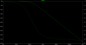
It has the potential for resonant peak but there's also a lot of resistance in series in this case. I'm using 5.6k in front of an EF86 in pentode mode, gain of ~50 so for a simulation I estimated 200pf Miller capacitance. The body of the Mills is 1/2 long, the inductance of 1" of wire 10 nH, so for the Mills an estimate of 20x was used, or 100 nH.
The result in LTSpice is shown below. It looks clean past 1 GHz. This is a rough estimate and neglects large inductive influences like input coupling caps, meter long interconnects, internal wiring, etc.. The Miller capicitance is also modelled as a perfect cap, i.e. self-inductance below 1 nH. If that's changed to 10 nH the response shows a strong null (no ESR in the model) just above 100 MHz and a clean rise towards 1 GHz, but by that point the model is so far out of it's assumptions it can no longer be trusted.
I think small value grid stoppers would be more vulnerable to this effect.
Edit: Forgot, there's 10 megohm in parallel with the Miller cap, it's a grid leak bias amp.
Attachments
Hi,
200pF for a EF86 in penthode mode?
That's seems awfully steep.
None of the interelectrode capacitances rise above 0.5pF for this tube.
Either way, the sim shows the wide bandwidth obtainable form a classic small signal penthode such as the popular EF86.
The graph would be a totally different story if the tube is subbed for a 12AX7A for example.
Also, as far as the pic of the MC preamp allows, it looks as if the shield of the tubes are just clamping the glass.
They don't seem to be grounded hence won't be very effective at shielding.
Should you really need the shielding to bring down humlevels then keep in mind that it adds a little stray capacitance to the circuit which may be responsible for a little roll-off.
Not that it should matter all that much, a MC pre doesn't need to be very wide bandwidth, most of it gets filtered out by the RIAA correction behind it anyhow.
Cheers,😉
I'm using 5.6k in front of an EF86 in pentode mode, gain of ~50 so for a simulation I estimated 200pf Miller capacitance.
200pF for a EF86 in penthode mode?
That's seems awfully steep.
None of the interelectrode capacitances rise above 0.5pF for this tube.
Either way, the sim shows the wide bandwidth obtainable form a classic small signal penthode such as the popular EF86.
The graph would be a totally different story if the tube is subbed for a 12AX7A for example.
Also, as far as the pic of the MC preamp allows, it looks as if the shield of the tubes are just clamping the glass.
They don't seem to be grounded hence won't be very effective at shielding.
Should you really need the shielding to bring down humlevels then keep in mind that it adds a little stray capacitance to the circuit which may be responsible for a little roll-off.
Not that it should matter all that much, a MC pre doesn't need to be very wide bandwidth, most of it gets filtered out by the RIAA correction behind it anyhow.
Cheers,😉
Did I displace a decimal? I though I read somewhere the value was 4 pf but that's what you get cranking this stuff while trying to be on time for work. To clarify the plot, it represents voltage to the input of the grid.
Hi!
Hmm - after few days I'm more dissapointed than not 🙁
The thing is - apparantely I have big problems with my PSU - I mean - todaj I wanted to listen to some music - but something strangely occured - the bass speaker membranes just moved in and out (with no sound) - well - then it settled down - I've tried to turn one record - and it again started over and over again - like something would lost the control ...
So I decided to measure voltages - the "heater" had only 5,9-6V instead of 6,3 - so I decided to measure AC - ONLY!! 208-210V ... OK I had enough of it and I'll decided to wait to get a more proper voltage - so at evening I tried again - this time AC was around 225-230V ... But quite soon it started again ... So I'll decided to investigate a little more - I've discovered our laundry washer is on and that my electrical radiator has A BIG influence ... Also turning the TV from shut down to STBY etc results in some very loud and "visual" pops in my speakers ...
And AND ALSO 🙁 the most scarry one - I switched off the preamp with volume knob opened - something bzzzzzd in speakers and then it pushed the membrane "IN" and it stayed there until I "closed" the volume knob .... ?!?!
SO I guess I have quite some work to be done!
So apparently I'll need to filtrate voltage somehow - so can anybodiy enlighten me a bit further what that grid filter is??
THANKS!
Welcome to the world of turn-on and turn-off nasties. That's something tube preamp builders have to live with- but it's very easy to incorporate a circuit that shorts the outputs to ground until warmup and does the same at shutdown or in the case of a power interruption.
The cone pumping is a classic symptom of motorboating- it means that your circuit is coupling unintentionally through the power supply, a positive feedback situation. You'll need to investigate separating out each B+ feed and bypassing them individually. An active regulator can be a GREAT help here.
Line filtering is a separate issue; there's been a lot of discussion about it, and some searching of the forum will yield great dividends. Morgan Jones does a nice treatment of this and the turn-on/turn-off issues in his book, FWIW.
Thanks SY.
I'll do a little redesign in future - hmm - interesting - today (monday) everything works more than OK 😀 But during the whole weekend - there was no way to use my preamp ...
I've done some "research" - it just happens that our house apparently is the last in the "row" of local electrical grid ... So that could explain a lot about nonstable AC in our house 🙁
I intend to use a bigger trannie - apparently the one used now has to big voltage fall under load to provide enough high voltage for regulator to have 6,3V - even today, when AC voltage is 230+V - I still have only 6V at the ouptut od PSU ...
I also intend to fiddle around with GND connections - apparently also the GND from the arm is somehow "loose" - if I move that connector a bit - the hum rapidly increases/decreases ....
So quite some stuff to be done ...
- Status
- Not open for further replies.
- Home
- Amplifiers
- Tubes / Valves
- New MC preamp is comming alive