Remembering screen grid modulation from my Ham days, I was thinking of a "new" way to introduce local feedback in a faux triode output stage. The Baby Huey, Simple PP and others have used Plate to Plate or Plate to Control grid FB for this purpose.
Is it feasible to use the screen grid as the element to introduce local feedback from the plate, through a resistive divider and blocking cap, to the screen grid?
Are there any benefits, other than the obvious ones of reducing distortion and Ri? Would it avoid the Zin problem of P-P or P-G feedback? [Zin=Rfb/(Gm*Rload+1)]
Last edited:
This idea has been suggested a number of times, including by myself. Jan Veiset has a thread here somewhere for a design like this. There are some issues to consider. Of course feedback to the output tube screen is standard UL mode, so I assume you refer to feedback to the driver screen.
The biggest issue is the low impedance of the screen(s). A follower of some kind is likely required in most cases. Next problem is that feedback to the driver screen grid requires crossed feedbacks from the output stage plates for proper neg. fdbk phasing. So P-P required. (ie. its just like neg. feedback to the driver grids, but with a less sensitive grid transconductance at g2, which can be helpful since one needs to attenuate the feedback anyway.)
Jan V. came up with a very interesting setup where the P-P driver screens were driven with feedback signals of a specific level that caused the driver plates to track the screens voltage-wise. This tracking effect should keep the current drawn by the g2 grids at a constant fraction of the plate current. So in this case the g2's look like linear resistive loads and could be driven without a follower. A very very interesting approach.
Next issue is that the g2 transconductance curves are a little different from the g1 gm curves. (not just gm magnitude, but curve shape) This is due to the grid wire "island effect" for g1. (close proximity of individual grid wires to the cathode causing local shadow effects) Grid G2 is far enough away from the cathode to not suffer this effect. So G2 feedbacks will not be so linear versus the input signal on G1. This can still be useful though. Lots of very linear neg. G1 feedback gives "clinical" sounding amplifiers, whereas lots of g2 feedback will still leave a triode gain signature (the plate in a triode similarly does not suffer from "island effect"). Only problem is that this triode signature effect gets largely lost in the even harmonic cancellation of the P-P configuration.
And yes, it would avoid lowering the driver g1 impedance, but you still have to deal with the low g2 impedance.
Oh, and another problem in general with crossed feedbacks, is that they are not so local anymore for class AB or B. This is because the feedback has to be generated from the undriven side of the output xfmr., so has to pass thru it. The low Z input at g2 then requires current to drive, if not buffered by a follower, so leakage inductance in the OT becomes a factor for phase shift.
Don
Last edited:
Here is a link to Jan's screen feedback design. I have not heard any more on developments with this for a while, perhaps Jan ran into stability problems. His design is quite involved with CFB to the driver as well. Perhaps he will drop in on the thread to update us.
Symmetrical Feedback Amplifier
I myself would suggest trying the screen feedbacks alone 1st, if someone tries experimenting with this. Jan's additional CFB feedbacks make McIntosh or Citation II designs look simple.
Some other variants I would suggest would be to use a constant current load on the plates of the driver pentodes. With tracking screen/plate voltages included in the workup, the screens should then draw constant current, making them high impedance. (you still have to supply about 10% of the constant driver plate currents to the screens from the feedback network though, could be another CCS). This will however make for very high loop gain in the driver/output feedback loop, so stability may become problematic.
Another variant or addition would be to use a small CFB winding in the output stage to supply the driver screen feedback signal source (well, with some DC voltage translation). Then it no longer needs P-P configuration to get the necessary fdbk signal inversion. And the feedback always comes from a driven (necessarily class A in SE) source, so no phase shift issues in the OT then. With SE mode, the "triode signature" of the driver stage will not be lost either, even with the very high loop gain when using a driver CCS plate load.
Lastly, and a bit afield here, dont' forget the other rarely used local feedback scheme. RCA and others used output stage plate to driver cathode feedbacks. This, in contrast to g2 fdbk, IS very linear. RCA used a combo of this and local Schade feedback in the designs in their tube data books. Combining a little fdbk each thru the various local schemes can allow one to tailor the sound, but gets complex fast.
Don
Last edited:
Feedback is feedback. You're better off adding it to the linear input, across the entire system, than trying to come up with some "novel" method which is harder to implement and performs worse.
Tim
Tim
Thanks. After reading more in RDH4, the interaction of all components must be taken into consideration. If it was that easy someone would have done it long ago. I have no delusions about coming up with something really new.
I once build a preamp based on g2 feedback. The idea was to run the pentode in triode mode but instead of connecting the g2 to the plate I included the cathode follower in the g2 loop: http://www.diyaudio.com/forums/tubes-valves/119821-gain-stage-g2-feedback.html
(The power amplifier with g2-feedback was never really accomplished. I ran into some stability problems and redesigned it..)
Jan E Veiset
An externally hosted image should be here but it was not working when we last tested it.
(The power amplifier with g2-feedback was never really accomplished. I ran into some stability problems and redesigned it..)
Jan E Veiset
Here again is my Pyramid -VII driver stage, it uses feedback by DC on the screen grid that stabilizes working points of all directly coupled tubes.
http://wavebourn.com/forum/download.php?id=119&f=7
http://wavebourn.com/forum/download.php?id=119&f=7
way back in the 80's there was a k to k nfb which i made up for an amp.
the amp was an ecl82 se with n.pass CCS enhance mosfet on the triode anode.
(the CCS was set so the enhancement was moved in to the bass)
several people made this type of amp back then for fun.
but one had an odd nfb, the cathode resistor was replaced with two resistors the sum of the original.
then a capacitor was run from between these resistors to the triode cathode.
it worked (in theory on a type of back bias)
i can't remember how well it worked, but i will be giv'ing it a try again soon.
I also thought about K-K feedback as I was investigating the feedback issue. Do you have a schematic with some real values? This could work well.
Cathode to cathode makes it look halfway like an LTP, which in turns means the grids start acting sort of differentially, which means putting one grid to the opposite plate is positive feedback. How much depends on how much it looks like an LTP. This will make an excellent Schmitt trigger, which doesn't do so well at quality audio reproduction.
Tim
Tim
Shmitt trigger when driver and output tube are DC coupled. If AC coupled, it may be an asymmetrical multivibrator. But if total CL gain by PFB loop is less than 1 the result may be a negative output resistance of the amp.
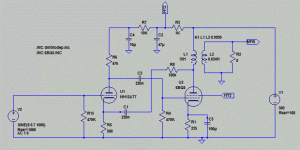
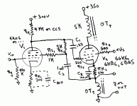
Svein's RH84 variant with feedback to the driver cathode looks interesting. I think I may break down and buy an Edcor SE xfmr to try out some RH84 variants (triode driver, pentode driver, driver CFB, ....) Playing around with that circuit, here is a rough start on a variant with feedback to the driver screen: (edit: Oops, forgot a 470K resistor from V2 grid 1 to ground for bias)
Jan Veiset's screen feedback preamp is similar to what I use for testing pentodes for linearity. I use an FQP1N50 Mosfet in place of the follower, with either a zener voltage drop or resistive divider from the Mosfet source to the pentode screen (with a screen stopper R too). Also, with a CCS for plate load of the pentode.
Don
Attachments
Last edited:
at that point we need to remember that the ECL82 with nelson pass ccs coscode EM mosfet.
was never meant to be "quality audio reproduction".
was never meant to be "quality audio reproduction".
it doesn't work out that way in an inversion.
IMO you would need to apply the cathode to cathode feedback over 3 stages if you wanted negative voltage feedback..
Some 2 stage tube phono stages commonly used cathode to cathode positive feedback to improve the feedback margins (available loop gain) for negative feedback based RIAA equalization, this supposedly increased the margin between the gain required for the proper LF response and the available loop gain for better accuracy. (and lower distortion) Examples of this technique can be found in commonly available Dynaco PAM-1, PAS-2, and PAS-3 pre-amps as well as others. In practice I am not sure just how well it actually worked.
Thanks for all of the "feedback." You have all straightend the kinks in my learning curve.
After reading more on the subject from literature that Pete Millett has so kindly posted, the Schade method of introducing fdbk from plate to grid caught my attention. I may contemplate this for a bit. An earlier thread http://www.diyaudio.com/forums/tubes-valves/153272-832-ultra-linear-push-pull.html caught my attention.
After reading more on the subject from literature that Pete Millett has so kindly posted, the Schade method of introducing fdbk from plate to grid caught my attention. I may contemplate this for a bit. An earlier thread http://www.diyaudio.com/forums/tubes-valves/153272-832-ultra-linear-push-pull.html caught my attention.
- Status
- Not open for further replies.
- Home
- Amplifiers
- Tubes / Valves
- New? Local Feedback Method


