Feed for thought
Interesting thread, Circlotron, as usual. You have demonstrated intriguing ways to apply linear feedback.
My is that what you want is to feed the input of the amp with the signal that produces the desired output, how you supply this input is the crux of the matter. This raises two questions: what input is needed to achieve the desired output and is there an input that will do it at all?
Conventional feedback is sort of doomed and thinking about it can cause ones head to . You input a signal S and get the signal plus an error e1 at the output. -e1 is fed back to the input causing an output change of -e1+e2. e2 is the error in amplifying -e1. Then -e2 is fed back and the output changes by -e2+e3, and so on. If this occured with infinite speed the amps input would end up being S-e1-e2-e3... and the input would be the exact signal needed to produce the desired output (provided the errors CONVERGE).
Now, the issue of convergeance is key. It is not possible to have an amp with infinite speed. The output response is delayed from the input. So the summation of the errors, as it were, is not simultaneous. Time cannot be reversed so the input never quite gets to where it needs to be. It follows that the faster the amp the quicker the errors will be eliminated. Also, the distribution of the errors with time will affect the input accuracy.
[I'm casually leaving out the basic issues of negative feedback implementation problems affecting the convergeance: like inaccurate error calculation and parasitic feedback paths and so on) to simplify my basic argument.]
Feedforward is an excellent way to overcome these problems. However, it is only as good as our prediction of what input is necessary to achieve the desired output. That's the rub. Since the output error will depend on unpredictable things, like speakers and temperature and the input signal history itself (electronics has memory - like thermal changes, capacitance, inductance and the speaker components and mechanical state) choosing useful feedforward is hard.
In summary, I'd say the ultimate goal is to determine the ultimate input signal. The quest for ultimate feedback is really a speed challenge. The quest for ultimate feedforward is a prediction challenge. In both cases we have to design a circuit that is capable of the desired output - not all are regardless of what we put into the input!
Interesting thread, Circlotron, as usual. You have demonstrated intriguing ways to apply linear feedback.
My
is that what you want is to feed the input of the amp with the signal that produces the desired output, how you supply this input is the crux of the matter. This raises two questions: what input is needed to achieve the desired output and is there an input that will do it at all?Conventional feedback is sort of doomed and thinking about it can cause ones head to
. You input a signal S and get the signal plus an error e1 at the output. -e1 is fed back to the input causing an output change of -e1+e2. e2 is the error in amplifying -e1. Then -e2 is fed back and the output changes by -e2+e3, and so on. If this occured with infinite speed the amps input would end up being S-e1-e2-e3... and the input would be the exact signal needed to produce the desired output (provided the errors CONVERGE).Now, the issue of convergeance is key. It is not possible to have an amp with infinite speed. The output response is delayed from the input. So the summation of the errors, as it were, is not simultaneous. Time cannot be reversed so the input never quite gets to where it needs to be. It follows that the faster the amp the quicker the errors will be eliminated. Also, the distribution of the errors with time will affect the input accuracy.
[I'm casually leaving out the basic issues of negative feedback implementation problems affecting the convergeance: like inaccurate error calculation and parasitic feedback paths and so on) to simplify my basic argument.]
Feedforward is an excellent way to overcome these problems. However, it is only as good as our prediction of what input is necessary to achieve the desired output. That's the rub. Since the output error will depend on unpredictable things, like speakers and temperature and the input signal history itself (electronics has memory - like thermal changes, capacitance, inductance and the speaker components and mechanical state) choosing useful feedforward is hard.
In summary, I'd say the ultimate goal is to determine the ultimate input signal. The quest for ultimate feedback is really a speed challenge. The quest for ultimate feedforward is a prediction challenge. In both cases we have to design a circuit that is capable of the desired output - not all are regardless of what we put into the input!
Interesting thread, and I'd like to add that I thought about it recently too. 🙂
Now to append to the thread:
The obvious solution, then, is to have the amplifiers fast enough, then apply limits to the FB/FF. Hearing dies at about 20kHz, say 30kHz for those hard-core types, so errors needn't attempt to correct anything so fast. A single-order filter can be used to trim this back. The amplifiers then need to keep up with this, and 1MHz devices aren't hard to come by AFAIK, so what's the big deal? (Aside from transit time of course, which IMHO leaves out op-amps and should be done with discretes in as few parts as possible.)
Tim
Jerald Graeme’s “Amplifier Applications of Op Amps” and “Optimizing Op Amp
Performance” books are perhaps the most accessible to address combined positive and negative feedback and stability (but not the power supply bootstrap)
The theory of power supply bootstrapping is old, but even modern pro’s get it wrong: Lanyi and Pisani “A High Impedance Buffer” IEEE Trans CAS-I v49, #8 aug 2002 (despite excellent and informative references they just didn’t “get it”)
From an article in preparation: (looks like I need to finish up soon, you guys are getting too close)
“Bootstrapping can lead to stability problems which are commonly misunderstood due to reliance on the “over” idealized op amp model. Simply recognizing that the op amp’s gain is developed with respect to the power supply pins allows accurate modeling both for writing transfer functions to formally explore circuit performance and for accurate simulation“
Spice modeling of op amp power supply bootstrapping is perilous, the standard Boyle op amp macromodel gain stage is connected internally to Spice node 0 (=gnd) and doesn’t model the effects of moving the supply voltage. BB/TI have a multiple-pole modeling technique that works; see the OPA227m <= look for the “m” spice model
Please call/email and annoy Analog Devices on this, their app note: AN-138 “SPICE Compatible Op Amp Macro-Models” gives a clear explanation and offers their own very good multiple-pole modeling technique – the difficulty is that they don’t actually use this model, the AD8610 model totally sucks, months of correspondence with Soufiane Bendaoud did not resolve the issues ( I guess he was too busy preparing his EDN article on Spice modeling to actually understand and correct the errors in his modeling technique)
Re: Calling Jan Didden...
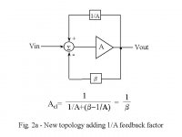
Well, to work exactly as you want it to work, the pos fb must have a precise value, in fact the reciproce of the forward gain of the " correction amp". If you look at the formula for the closed loop, the A/(1+beta.A), if your pos fb is just right you add a factor to the equation to remove the "1", so it becomes A/(beta.A) which of course reduces to 1/beta, and then whatever A (the power output stage) does becomes irrelevant.
When I played with this, I made a graph adjusting the pos feedback and looking at the THD. When you start from a pos fb too low and increase it, the THD drops to a minimum when the pos fb matches the forward gain. Increasing the pos fb any further increases the THD again, but the distortion signal will have flipped through 180 deg phase shift. The min THD depends on the corretion amp thd multiplied by the pos fb factor.
Jan Didden
PS I really haven't given up on this concept, still a few options I'm pursuing but will keep to myself for the time being. But you may get there first. I you like complex calculations...
Circlotron said:Jan, I was re-reading the other day those papers you sent me, and thinking further about the opamp approach for this kind of cct, it appears that the positive feedback path merely nullifies the negative feedback path to any extent you want (or more!). Even though the opamp may only have an aparent gain of 2 because of the negative feedback resistors and therefore hopefully nice and stable when the loop is closed around the next device e.g. emitter follower, the positive feedback path makes the + input of the opamp move the same direction as the - input causing the output to have to swing much further to satisfy the feedback loop. I can't see the difference between that and simply raising the value of the nfb resistor and having no pfb. The end result appears to be the same in practice. What do you think?
Well, to work exactly as you want it to work, the pos fb must have a precise value, in fact the reciproce of the forward gain of the " correction amp". If you look at the formula for the closed loop, the A/(1+beta.A), if your pos fb is just right you add a factor to the equation to remove the "1", so it becomes A/(beta.A) which of course reduces to 1/beta, and then whatever A (the power output stage) does becomes irrelevant.
When I played with this, I made a graph adjusting the pos feedback and looking at the THD. When you start from a pos fb too low and increase it, the THD drops to a minimum when the pos fb matches the forward gain. Increasing the pos fb any further increases the THD again, but the distortion signal will have flipped through 180 deg phase shift. The min THD depends on the corretion amp thd multiplied by the pos fb factor.
Jan Didden
PS I really haven't given up on this concept, still a few options I'm pursuing but will keep to myself for the time being. But you may get there first. I you like complex calculations...
jcx said:Jerald Graeme’s “Amplifier Applications of Op Amps” and “Optimizing Op Amp
Performance” books are perhaps the most accessible to address combined positive and negative feedback and stability (but not the power supply bootstrap)
[snip]
In fact I have been in contact with Jerry about my little circuit, which he admitted he hadn't seen before. BUT, I then later learned it had been patented in 1953 or therabouts.
" There is nothing new under the sun, but there is a lot we haven't seen yet " -- Anon
Jan Didden
Jan...
I am very interested in your paper and references as well, my local university library dropped the AES preprints
addr=xocj[at_sign]netzero[dot]net
thanx
I am very interested in your paper and references as well, my local university library dropped the AES preprints
addr=xocj[at_sign]netzero[dot]net
thanx


Ahhhhh, but it works so much better in the digital domain.... 🙂
This thread brings back memories of working on digital control loops and having combinations of feed-forward loops, essentially taking a working knowledge of the "plant" and linearizing the output, then using overall negative feedback to maximize accuracy. You can find lots of text book material on control systems which in the end is essentially what a power amplifier is. I suggest anyone working on power amps to do some reading on control theory as it will give you a real good understanding of the math, the effects of feedback, etc.
Circlotron, it is a novel architecture. I would simulate it for you, but I am concerned as others have pointed out, that the spice models I have would not be sufficient to realize what is really happening.
When you apply feed forward, you normally are taking your knowledge of how the "plant" or in this case the output buffer works and essentially guessing what correction is needed to eliminate any known non-linearities in the output. If you are not doing this, then essentially, all you are doing is increasing the loop gain which is what I think you may be doing? This will be born out in the system equation. Overall, that does not mean it is a bad thing. Now if you start adding some non-linearities to match the non-linearities in the output stage......
Alvaius
I concur with alvaius,
Jannemans mathematical conjuring to remove A from the equation are really smoke and mirrors (sorry 🙁 ) and are simply different ways of applying different open loop gains.
The key is to deal with non-linearities. Is the best way to apply linear, negative feedback? No, of course not. The best way is to eliminate the distortion by removing it or pre-compensating for it. The latter is hard work, both in measurement and treatment.
When people are taught about feedback theory they are first, and often only, taught about feedback in linear systems. Well, whipdy-do! Easy, easy, easy.
Welcome to audio - "non-linear systems extraordinaire!" The same rules don't apply the same way anymore. 😱
Yep, that's what I think I am doing alright. I was really excited about the whole thing until I thought about it this way. I can't do the hard sums behind all of it so I just think intuitively and build and observe and measure.alvaius said:If you are not doing this, then essentially, all you are doing is increasing the loop gain which is what I think you may be doing?
Alvaius
What I would like to try one day is turn serial digital audio into parallel with a shift register then use this 16 bit number to address a rom where a pre-corrected version of the sample resides. Use this sample to feed the amplifier. Maybe even self-learning where a nfb loop determines how close the output is to ideal and if it is too far off then it adds or subtracts from the signal as necessary (the forward path signal remains unchanged, only the feedback signal is fiddled) and digitises and writes this corrected data point back to the RAM. Next time around it would be closer and so wouldn't need the rewrite. Perhaps a bit tricky for me though.

traderbam said:I concur with alvaius,
Jannemans mathematical conjuring to remove A from the equation are really smoke and mirrors (sorry 🙁 ) and are simply different ways of applying different open loop gains.
The key is to deal with non-linearities. Is the best way to apply linear, negative feedback? No, of course not. The best way is to eliminate the distortion by removing it or pre-compensating for it. The latter is hard work, both in measurement and treatment.
When people are taught about feedback theory they are first, and often only, taught about feedback in linear systems. Well, whipdy-do! Easy, easy, easy.
Welcome to audio - "non-linear systems extraordinaire!" The same rules don't apply the same way anymore. 😱
Well, I would be willing to concur with alvaius if I only knew what he was saying, beyond the generalities.
I think you didn't grasp the full width of my little circuit. What happens is that the properties of the output stage A, are absent from the output. That includes THD, noise, offset etc. Not reduced, absent. True, we still have to cope with the TDH of the summer block, but as far as the A block is concerned, its THD contribution to the output is zero. Not very small, zero. What more do you want?
It may all be smoke and mirrors, but you need to be more specific than such an off-hand remark to help me understand this better.
Jan Didden
Jan
Consider a physical implementation of the amplifier block A.
Given an input signal Vi, the output of this block will be
A*Vi+f(Vi)
where f is a function that corresponds to distorsion
products, noise etc. The problem with your circuit is that your
feedback block must implement the inverse of this function,
that is,
1/(Vi*A+f(Vi))
and not just 1/(Vi*A).
Edit: Actually, I realize now that even this was way too much
simplified. One would have to implement some even nastier
function, but I think the above should at least visualize the
problems with this approach.
Buzz Lightyear
Jan,
Sorry for being rather off hand, I was in a hurry . Christer raises a good point too: that making 1/A is practically very difficult. However, my point is simply this - you cannot remove the affect of a component in a signal path, completely, unless you are applying infinite feedback or a perfect pre-compensator.
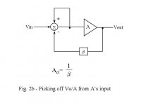
Take circuit 2b. There is no finite solution to the summer output voltage unless Vin = BVout exactly. In any other case the summer output will be infinite. This is because the summer output is fed back to its input - positive feedback. Consider the case when A=0; it most certainly has an affect on the transfer function. The maths includes the assumption of infinite gain: the summer is now effectively an op-amp with infinite gain.
In the first circuit you have employed the perfect pre-compensator and then apply infinite feedback as well. I reason that if it were possible to make 1/A then why not make n/A and put it in series with A as a precomp, thus avoiding any feedback at all? In this case the transfer function would be n.
Jan,
Sorry for being rather off hand, I was in a hurry
. Christer raises a good point too: that making 1/A is practically very difficult. However, my point is simply this - you cannot remove the affect of a component in a signal path, completely, unless you are applying infinite feedback or a perfect pre-compensator.Take circuit 2b. There is no finite solution to the summer output voltage unless Vin = BVout exactly. In any other case the summer output will be infinite. This is because the summer output is fed back to its input - positive feedback. Consider the case when A=0; it most certainly has an affect on the transfer function. The maths includes the assumption of infinite gain: the summer is now effectively an op-amp with infinite gain.
In the first circuit you have employed the perfect pre-compensator and then apply infinite feedback as well. I reason that if it were possible to make 1/A then why not make n/A and put it in series with A as a precomp, thus avoiding any feedback at all? In this case the transfer function would be n.
New Fb
Christer, now we're getting somewhere!
Of course I don't agree: the output of the system Vo=A*Va+f(Va), where Va is the input to the A-block, and f(Va) is the noise, distortion etc generated inside A, as you noted.
Referring to my last diagram, if you calculate Va as function of Vi and beta*Vo, and make that equal to Vo/A (which is Va of course), it will become very clear how such a simple circuit can be very elegant: A disappears!
I don't have time now, but will post the calculation this evening.
Jan Didden
PS Just saw Traderbam's post: 1/A is very easy to make, or rather: 1/A*Vo, because that is Va! (See 2nd diagram). Realising that was a huge time saver for me. And yes, A must not be zero, agreed. A must always be positive in this application. Your last point is interesting, let me think about it.
Jan
I will be interesting to see your calculations Jan. I just made
some more precise calculations myself and it is very difficult
to see how the error could be cancelled, unless you make some
very strong assumptions about the error function.
some more precise calculations myself and it is very difficult
to see how the error could be cancelled, unless you make some
very strong assumptions about the error function.
fb
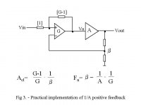
Referring to my 3rd diagram in the earlier post:
First calculate the V+ and V- input voltages at the summer block:
The contribution of Va to V+ = 1/G*Va = Va/G; the contribution from Vi = (G-1)/G * Vi, so by superposition V+ = [Va/G + (G-1)/G*Vi).
V- = b*Vo (I'll use b to indicate beta, the nfb factor)
Since Va = G*(V+-V-), Va= G*[Va/G + (G-1)/G*Vi - b*Vo] = Va + (G-1)*Vi - G*b*Vo.
You're still with me? OK: subtract Va on both sides, you get:
(G-1)*Vi-G*b*Vo=0.
So, (G-1)*Vi=G*b*Vo, therefor Vo/Vi = (G-1)/G*b. No A. (The attenuation factor (G-1)/G comes from the fact that Vi is attenuated this amount by the pos fb network). QED. There are other ways to get the same result, like substituting Va=Vo/A, but the result is the same.
Jan Didden.
PS Just in case you guys think that this is a purely theoretical exercise, I have built a power amp using this concept and will post some measurement results later.
Jan,
There is nothing wrong with your algebra. My earlier point is that when the closed loop gain is evaluated an "infinity" is assumed. If you try calculating the open loop gain you may see what I mean.
BAM
There is nothing wrong with your algebra. My earlier point is that when the closed loop gain is evaluated an "infinity" is assumed. If you try calculating the open loop gain you may see what I mean.
BAM
Jan;
Setting your positive feedback to 1/G is still begging the question. I believe keeping the positive feedback separately labeled prevents premature cancellation.
The following reduces to your "ideal" relation when Beta_p = 1/G but clearly shows what occurs where that identity is inexact:
A is now seen to have the normal role in negative feedback error reduction
It is physically impossible for Beta_p to equal 1/G over all frequencies as any real amplifier G must ultimately be low pass, requiring Beta_p to become an ideal differentiator at high frequencies. This doesn't preclude the equality being approximately met at low frequencies and for the circuit to have extremely high loop gain at these low frequencies.
Attachments
- Status
- Not open for further replies.
- Home
- Amplifiers
- Solid State
- New kind of feedback or just re-inventing the wheel?