Hi all,
what do you think of this? I haven't seen this topology anywhere. Am I missing something or is this a great way to overcome limitations of JFET switches:
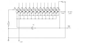
- no current actually passes the JFET. It is just used as a switch passing voltage to the inverting op amp input - the inv input being essentially a voltage sensor anyway and not a load
- R(DS) should therefore remain constant
- any minor variations in R(DS) will be insubstantial compared to the input impedance of the op amp.
Potential for problems would be
- nonlinearity for bipolar voltages - however at virtual ground there won't even ever be any V(DS) *or* I(DS)
- leakage of control voltage of the JFET - however, again, at virtual ground on one end and "infinite" input impedance on the other that shouldn't be a problem.
Have a found the elusive non-distorting JFET switch application?
MBK
what do you think of this? I haven't seen this topology anywhere. Am I missing something or is this a great way to overcome limitations of JFET switches:
- no current actually passes the JFET. It is just used as a switch passing voltage to the inverting op amp input - the inv input being essentially a voltage sensor anyway and not a load
- R(DS) should therefore remain constant
- any minor variations in R(DS) will be insubstantial compared to the input impedance of the op amp.
Potential for problems would be
- nonlinearity for bipolar voltages - however at virtual ground there won't even ever be any V(DS) *or* I(DS)
- leakage of control voltage of the JFET - however, again, at virtual ground on one end and "infinite" input impedance on the other that shouldn't be a problem.
Have a found the elusive non-distorting JFET switch application?
MBK
Attachments
hey thanks, I thought I'd never get any interest from the forum for the stuff *I* think is interesting 😉
MBK
MBK
Nonlinearity would be my concern too. Isn't that the basic problem with commercial analog switches?
Also be aware that the drain-source capacitance of FET's goes way up when there's no DC voltage on them.
Try it and report back.
Also be aware that the drain-source capacitance of FET's goes way up when there's no DC voltage on them.
Try it and report back.
actually I've tried it
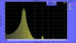
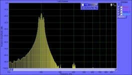
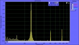
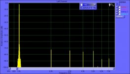
... with 2 stages (not the full R ladder), one JFET "on", the other "off", and a TL072. Didn't listen, but did distortion tests. My soundcard is not the greatest I'm afraid, but at least I see no difference between just resistors, and resistors plus the switch. Photos of distortion spectra below. The source was test CD's with either sine waves (250 and 1000 Hz) or a 200 Hz sine wave modulated tone burst (Linkwitz test CD). The sine measurements show distortion which is equal to the passive R setup and the JFET setup; this may have come from the source recording or another limiting factor. The burst spectra are cleaner. The noise floor especially below 200 Hz mocks things up a little. Regardless - I see no difference at this stage and with this equipment, between passive resistor divider on the inv input, or a JFET switch.
MBK

JFET’s as switches can work quite well, however to simplify the design I would use a device like a Siliconix a DG180 or 181 that can be controlled by TTL signal. Some devices on the market like the 4000 series cmos switches are not so hot.
As far as linearity is concerned these devices can be and they low noise performance good isolation and thermal performance. Of course the on resistance and the capacitance or just some of the important issues. Siliconix offers a many different types of FET designed for switches. Look for one that are used for high performance sample & hold multiplexer, where leakage, on-resistance and charge injection isolation are critical in the performance.
The also work well in feed back loops, however I am not that found of using the devices as an attenuator in that arrangement.
I'm not following what is going on here, but I'm aware that MAX313s are very good analog switches (low on resistance, low leakage currents): http://pdfserv.maxim-ic.com/en/ds/MAX312-MAX314.pdf
JF
JF
Thanks for pointing me towards devices specifically designed for switch applications.
The point of my design however, if my assumptions are correct, is that it truly removes the switch from the signal path. In my circuit, the JFET simply switches the (-)input of the op amp "into" the various positions of the voltage dividers formed by the resistor array, the same way as a pot wiper would. The (-) input with its practically infinite input impedance solely acts as a voltage sensor. If you use a FET input op amp, the JFET switch at the (-) input never passes any current, unlike in all other topologies I have seen, where the JFET is usually placed in either the input signal path, or the feedback path, with op amp virtual ground on one end. These topologies leave open questions as to JFET nonlinearities dependent on signal voltage and current.
My topology just uses the JFET as a one way extension of the op amp input. It allows the (-) input to sense the voltage at various positions of a passive resistor array that passes the signal. Therefore it *should* (and this is my unanswered open question) be immune to most (all?) nonlinearities of the JFET switch.
MBK
- Status
- Not open for further replies.
- Home
- Amplifiers
- Solid State
- New JFET switched volume control