New IR Control Desing
I'm starting to work on my new IR remote control for preamp.
I red a lot of posts on this site but was never satisfy with the different approach. I knew the Basic Stamp and like the way I can easily change and experiment with it.
My first protype of IR receiver/decoder is working. 😎
The IR receiver and decoder is based on the work of Michael Owings. See is excellent work at: http://www.swampgas.com/robotics/irremote/
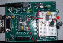
The receiver is using an PIC12C508 MCU and a Sharp IS1U621L IR receiver. All parts can be obtained easily from Digikey. It accepts any Sony remote.
The control will be done using a BasicStamp2. The preamp display will be a BasicStamp serial compatible LCD.
A led is also included that flash with the IR received.
I'm using a BasicStamp2 kit to read the code at the moment.
This kit will be used in my next Classe Clone Preamp and my future XBOSOZ Preamp.
Schematic, Bill of material and code will follow...
Picture of the prototype:
I'm starting to work on my new IR remote control for preamp.
I red a lot of posts on this site but was never satisfy with the different approach. I knew the Basic Stamp and like the way I can easily change and experiment with it.
My first protype of IR receiver/decoder is working. 😎
The IR receiver and decoder is based on the work of Michael Owings. See is excellent work at: http://www.swampgas.com/robotics/irremote/
The receiver is using an PIC12C508 MCU and a Sharp IS1U621L IR receiver. All parts can be obtained easily from Digikey. It accepts any Sony remote.
The control will be done using a BasicStamp2. The preamp display will be a BasicStamp serial compatible LCD.
A led is also included that flash with the IR received.
I'm using a BasicStamp2 kit to read the code at the moment.
This kit will be used in my next Classe Clone Preamp and my future XBOSOZ Preamp.
Schematic, Bill of material and code will follow...
Picture of the prototype:
Attachments
Member
Joined 2002
Congratulations with your new decoder !
Since you mention preamps as the host for your IR remote project you are invited to have a look at http://home1.stofanet.dk/hvaba/fprc5rx/index.html (in case you haven't already). Its a decoder project that initially started as a means to build a remote controlled standard analog preamp. I have no idea if this is something you might find interesting or not 🙂
 Warning - this is a slick piece of self-promotion !!
Since you mention preamps as the host for your IR remote project you are invited to have a look at http://home1.stofanet.dk/hvaba/fprc5rx/index.html (in case you haven't already). Its a decoder project that initially started as a means to build a remote controlled standard analog preamp. I have no idea if this is something you might find interesting or not 🙂
Warning - this is a slick piece of self-promotion !! Great site
Thanks. A lot of interesting links. However the source code is not there. My version will offer full programmibilty using the Stamp and I will share all my code.
Thanks again.
Thanks. A lot of interesting links. However the source code is not there. My version will offer full programmibilty using the Stamp and I will share all my code.
Thanks again.
More 'self promotion'. Hit www below if you want code for a pic for decoding RC5.
The code is a bit unusual, it is a statemachine written in sw.
Not my idea btw.
GuidoB
The code is a bit unusual, it is a statemachine written in sw.
Not my idea btw.
GuidoB
Actual Prototype
Here my actual prototype of a motorized volume control preamp version. It used the Sony PIC predecoding IC for the IR remote codes. The preamp includes some nice features for now:
Features supported:
-Motorized Volume Pot. control with Min & Max course position detection (optional)
-Source, Mute and Stanby functions
-5 Relays source control
-Mute and Standby Functions
-Relays drivers IC and PCF8574 port expander I2C bus (for additional relays control)
-Mute actived during Source change to reduce switching noise.
-ESD buttons protection (like the APOX)
The actual prototype is not fully functionnal yet. Debugged functions are:
-Manuals (buttons) functions
-I2C functions OK
The remote control integration is not completed yet.
Take note that this schematic is the control section only. You need to integrate that to your preamp desing.
Feel free to work on this desing and keep me posted.
Bye.
Attachments
if anyone is interested, i have code for the RC5 Philips protocol...it is in C for PIC16F877, but you can change it for any processor...it was originally for a real time clock that you could change the time with a universal remote control..feel free to email me if you would like the code
Member
Joined 2002
No big deal. Here the input selection of my preamp project.
It has just 4 inputs but you can easily add others.
The Basic Stamp program can also easily be modify for the number of inputs that you have. Just change in the initialisation section, init:, the variable CH_cnt to the number of inputs to select, ex. for 5 channels:
CH_cnt = $05 ' Set CH1 as Channel Count
Bye...
Attachments
Is this what you plan to make?
Algar_emi,
Is this what you plan to make?
Cheers, -ALBQ
http://mywebpages.comcast.net/gillespie147/12AU7-Preamp.html
Algar_emi,
Is this what you plan to make?
Cheers, -ALBQ
http://mywebpages.comcast.net/gillespie147/12AU7-Preamp.html
Yes, exactly, but I was never able to get your source code and schematic, so I decided to build my own, byt it takes time. If you can provide me with the source and schematic, I would really appreciate. My version support I2C IéO expansion thought.
My bigger plan was to build a kind of modular preamp where I could experiment with different supplies and preamp circuit. I what to have a general control and source selection section.
Any help would be appreciated. My control section for the volume control is still not perfect and can be improved. To see other example of implentation can cut development time.
Thanks again...
SB
Hi,
Not shure what you problem is with volume, but maybe you could benefit from knowing the position of it (and not only begin and end). Can be done with a bourns decoder attached to the volumepot-shaft.
Or build one with relays/resistors. Better quality...😱 (havent done yet myself, only 'hearsay'.
Not shure what you problem is with volume, but maybe you could benefit from knowing the position of it (and not only begin and end). Can be done with a bourns decoder attached to the volumepot-shaft.
Or build one with relays/resistors. Better quality...😱 (havent done yet myself, only 'hearsay'.
Reguarding the motorized motor volume, I tought about this problem for some time. Most commercial product that are using this type of control don't have any kind of pot read back. The pot used has a clutch mounted on the motor gear box. The volume is turn down at start up, then usually a led or a color mark on the volume knob indicate the volume position to the user. Then you adjust the volume by ear...
When my preamp turn on, the pot is activated for a period long enough to turn it down from full max. The pot's clutch let the motor turn even if the pot is at minimum. Then I simply activate the up/down line for as long as requested.
One way to detect the Min/Max position is to sense the motor current. It increases by a significant margin when the motor pot hits the stop. But I found this to be unnecessary complexity in this application.
The mute function can be implemented by shorting the preamp output to gnd (if the preamp output circuit can live with it) or by opening the output, all with a relay.
Starting point
Algar_emi,
Sorry but, I do not remember you ever asking me for the schematic/source code???
As far as my preamp is concerned, I never actually committed digital section of the schematic to paper but, it is realatively simple and for the sake of enabling other people to extend upon the basic design, am willing to try. As a starting point, here is the by far the most difficult part of the the thing to figure out - the source code
Enjoy -ALBQ
Attachments
Thanks for the code. Interesting reading. It will be easier to decode with the hardware schematic.
If you can provide me with a hand drawing, even something done fast, I can post a nice cad version for you and the rest of the members. Thanks.
If you can provide me with a hand drawing, even something done fast, I can post a nice cad version for you and the rest of the members. Thanks.
Member
Joined 2002
So how are things going with this.. I got my lcd from Elkaid. and will be starting my project pretty quick here. Going to order some parts next week all the psu parts and some other goodies..
Will try and work on it
Algar_emi,
I will try and work on it over the weekend. I am a bit busy today and tomorrow but, will try to get something something draw - will need to pop the cover on my preamp as its been a while =^)
Just with the source code, you should be able to get the IR decode and display working - as well as be able to toggle the condition of the output pins. The IR detector connects directly to the stamp (the detector has 38khz filter build in) and the display routine should drive any serial LCD (many need to adjust biginning/end of each line and baud). Rest of the pins are used for outputs and are simply toggled or held high/low
Cheers -ALBQ
PS. I have always planned to revise the design. Once you get your breadboarded version up an running, we should talk about the ideas/changes I did not get around to implementing - Audio projects are like movies, they are never really done. Its just that the director stopped working on it
Thanks. Yes, that is a good idea. I'm very busy myself all summer. My audio projects usually go ahead when the weather turns cold outside. We'll see what we can do. 😀
- Status
- Not open for further replies.
- Home
- Amplifiers
- Solid State
- New IR Control Design