I picked up this old phono amp and rebuilt it to a modified Deluxe 5e3 with Judge Roy Bean tone stack.
This is my first scratch build, I modified the schematic and built the circuit from that. It sounds ok but there's something funky about the dirty side. It sounds ok if you keep the volume way down but it gets quite a bit louder and produces squealing sounds as you turn it up. The clean side is pretty nice but not real clean. It sounds better with a 5v4 rectifier.
Is there anything obviously whacked in the schematic?
Voltages with 5v4 rectifier and 366v B+
12ax7 (1)
Clean: pl 1= 144v, pl 2= 173v, k1= 1.18v, k2= 1.24v
Dirty: pl 1= 144v, pl 2= 186v, k1= 1.0v, k2= 1.55v
12ax7 (2)
Clean: pl 1= 241v, pl 2= 201v, k1= 2.96v, k2= 56.7v
Dirty: pl 1= 140v, pl 2= 191v, k1= 1.02v, k2= 54v
6v6's: plates 348v, screens 324v, cathode 21v
Thanks
Attachments
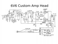
How do you get any clean sounds at all with the volume pot after two cascaded 12AX7s? Normally the volume (gain) pot is placed between first gain stage and the second, so the second isn't overdriven at all times.
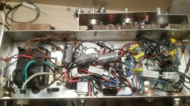
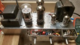
Impossible to see how your wiring is laid out. The signal - return, as well as the b+ with return, is critical with high gain ckts.
Other than that I'd lower the signal cap values a bit. See attached for some suggestions. I've also experienced that no matter how fine the layout, when the volume (or 'gain') pot is maxed out, the amps will often squeel like mad pigs. A 10kohm resistor right before the pot fixes that.
Grid stopper is very important to have right at the socket as close as possible to the grid.
That phase inverter is very good but does not like to be loaded heavily, which it is when over driving the output. Lower value caps and larger grid stopper helps. Even up to 100kohms can be used on the grids of 6V6s.
Edit: the selector switch for feedback or no feedback dosnt look right, see my scetching.
Attachments

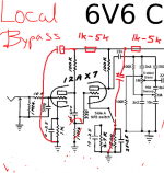
The two diodes at the plate of the 5Y3 are absolutely unnecessary. You can remove them.
Actually they are good insurance against hot arcing during transient conditions, inadvertent power cycling, etc., and do no harm. They are absolutely mandatory with modern production 5AR4. They should not be necessary with NOS 5Y3 but can't hurt and will permit the substitution of a 5AR4 for less sag if desired.
I use them wherever 5AR4 are employed in my designs.
Thanks for the great replies, especially SemperFi, this forum is awesome! I've studied a lot but this my first post.
I made most of the revisions SemperFi suggested but I need some guidance on the value of the "motor boating" bypass caps.
I put the diodes in before the rectifier because I thought they were supposed to protect the rest of the circuit if the rectifier fails in a bad way. I guess it's just for the 5AR4 type?
I think I'll make the other corrections first and then address the cap values.
I will put the grid stopper as close as possible, as suggested.
Thanks
Attachments
To prevent motor-boating it'd be enuff with a cap value of a few uF, but since you have 1kohm in series with the b+ you can create a LP-filter to kill some rectifier ripple as well. 22uF is a decent value. So 10uF - 47uF depending on what you have laying around.
Many purists don't like too high cap values since they feel it kills some responsiveness. I havent been able to detect that so I just use a reasonable value I have at hand.
Oh try to elevate the heater to a voltage between 10-80V. You can always settle with grounding the heater, but there will be some heater AC creeping into the cathodes and with high gain as in this case it may be objectionable. Tying one end of the heater wiring to the 6V6 cathode is a nice try. (When the heater is at a potential higher than the cathodes of the sensitive preamp tubes, no electrons will flow from the heater to the cathodes, eliminating hum from the heaters).
Since preamps run mostly in Class A, and only draw a few mA of current, there's no basis to the idea of larger filter caps killing responsiveness. If anything, the large caps would make the preamp faster and snappier in response. However, for the reasons already given, it's extremely unlikely.Many purists don't like too high cap values since they feel it kills some responsiveness. I havent been able to detect that so I just use a reasonable value I have at hand.
Some people do like to use smaller cathode caps on the power tubes to increase the saggy feel of a cathode- biased amp.
Sent from my LG-D801 using Tapatalk
Last edited:
You know, if I was doing this project, I think I would might like to build the PI/PA end as a 5D3 Deluxe instead of a 5E3. IMO the 5D3 with its paraphase PI sounds warmer than the 5E3, with an almost like buttery sweet tone (for lack of better words) http://www.thetubestore.com/lib/thetubestore/schematics/Fender/Fender-Deluxe-5D3-Schematic.pdf
You know, if I was doing this project, I think I would might like to build the PI/PA end as a 5D3 Deluxe instead of a 5E3.
Interesting. I'd like to build an amp with both types. With a switch to select one or the other and have as many as possible do a/b tests for me.
But I think Id stick to the cathodyne on this one. It can be buttery smooth too but it must be lightly loaded.
- Status
- Not open for further replies.
- Home
- Live Sound
- Instruments and Amps
- New guitar amp build and schematic help