Hi All, 🙂
I'm new to this forum and have read quite a number of posts in this forum.
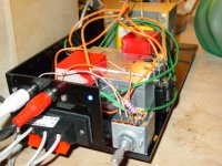
I have just completed a gainclone prototype using the LM1875 yesterday. This little baby working in inverting mode and the first impression to me is clean and tight bass, sweet highs but the mids is a bit cool (may be for me only 😉 ).
Will let it burn in for some more time. Pics will be ready soon.
The result is quite encouraging and I'm ready to built the LM3875 clone now. 😀
cheers
I'm new to this forum and have read quite a number of posts in this forum.
I have just completed a gainclone prototype using the LM1875 yesterday. This little baby working in inverting mode and the first impression to me is clean and tight bass, sweet highs but the mids is a bit cool (may be for me only 😉 ).
Will let it burn in for some more time. Pics will be ready soon.
The result is quite encouraging and I'm ready to built the LM3875 clone now. 😀
cheers
Welcome to the club mdlover!
Give it a bit longer to burn in. But what type of resistors are you using. You could do try a carbon film for the input resistor!
This little baby working in inverting mode and the first impression to me is clean and tight bass, sweet highs but the mids is a bit cool (may be for me only ).
Give it a bit longer to burn in. But what type of resistors are you using. You could do try a carbon film for the input resistor!
Hi,
The resistors in the signal path are all Holco. The one you see with color rings is for the LED and is removed already.
Coz I just got the Holco on hand and the feedback is 200K instead of 220K but the gain drop is no harm.
Since this is a prototype, all components are just from my toolbox. I have prepared the LM3875, Riken, Blackgate and ...... 😀
ps, is there a big difference between different input coupling caps? like wima, kimber cap and the blackgate
cheers
mdlover
What you describe is in my experience the sonic signatire of the 1875. The 3875 has better bass and warmer mids and generally calmer sound. The Wima caps and spring-loaded terminals also don't help much.
cheers
peter
What you describe is in my experience the sonic signatire of the 1875. The 3875 has better bass and warmer mids and generally calmer sound. The Wima caps and spring-loaded terminals also don't help much.
cheers
peter
ps, is there a big difference between different input coupling caps? like wima, kimber cap and the blackgate
Not sure about BIG difference but there is a difference. To save you reading all the posts here (although it is very elightening to do so) I would say that most GC builders prefer either a Black Gate (N or better) or a polypropyline (or nothing at all if there is no DC from the source).
elizard said:yeah, welcome to the gainclone cult 🙂
yeah, the new gc using 3875 is in progress now.... 😉
but after reading Perter Daniel's post, I'm jealous about his wonderful housing for the gc.

analog_sa said:mdlover
What you describe is in my experience the sonic signatire of the 1875. The 3875 has better bass and warmer mids and generally calmer sound. The Wima caps and spring-loaded terminals also don't help much.
cheers
peter
will compare the sound soon, the new gc using 3875 is in progress 😉
cheers
Yo~! Guys...any one tried Mylar caps?? they are called polester caps as well...cheap though....
Yup. We know what are polyester caps. The perfect choice if you aim for cheap sound 🙂
Hmm...meaning it would be good as well...for a cheapo one at least...I have built some tube amps..and I always use Mylar caps...better than those crappy wax paper caps I always see...and they melt when u apply solder near to their "ends"...I guss I will go with Mylar caps..I'm on a really limited budget here...just ordered for some LM3875TFs...insulated tabs...hehehe...I gonna kick a** (self-censoring)
Well, there are many ways to kill the 3875 sound... Can't you at least manage a WIMA MKP4? I use no cap as preamp is either cap or transformer coupled.
Where in Singapore would be the best place to get quality input caps?? I got the LM3875 free as a sample from National Semiconductors...resistors I plan to use 1% metal film and Panasonic alumninium electrolytics...any reason why not to go with RubyCon caps?? I heard they are bad...wonder why??
Nuuk said:
(or nothing at all if there is no DC from the source).
Hi Nuuk.
Have you tested it?
I did.
With no DC from the source and no input cap, source playing, no input cap and measuring DC: as the music is playing, DC varies from a few mv to about 900 mv!😱

I wouldn't advise to use a GC with no input cap.
mdlover, good one, and a good first prototype.
But let me give you a suggestion: put the PSU caps closer to the chip, it has long pins, you can cut them.
P-P is definitely not for me, I do smaller and tighter with breadboard.
Try the LM3875, you'll have a surprize.
As a matter of fact, I'm doing things the other way around: first, the LM3875, then the LM3886 and yesterday I made a little board with two LM1875s.
My idea is to make what will probably be the smallest GC in the world.😀
Went to bed at 2 am, two resistors before finishing it.

With no DC from the source and no input cap, source playing, no input cap and measuring DC: as the music is playing, DC varies from a few mv to about 900 mv!
Carlos
Do you realise the above does not actually make much sense? Whether the cap is in the source or in the amp, or there is some other way of blocking dc you get a pretty stable offset , whether music is playing or not. I have tested the variations of offset with temperature and they're very minor. How did you conduct your measurement?
cheers
peter
analog_sa said:
Carlos
Do you realise the above does not actually make much sense? Whether the cap is in the source or in the amp, or there is some other way of blocking dc you get a pretty stable offset , whether music is playing or not. I have tested the variations of offset with temperature and they're very minor. How did you conduct your measurement?
cheers
peter
I had around 28 mv on one channel with the LM3886.
I wanted to try, and shorted the input cap with a wire.
DC was the same.
I pressed play on my portable MD player and measured as the music was playing.
And I measured huge variations in DC offset.
Test it and you'll see.
I think these chips really need an input cap, as normally bipolar devices do.
Maby the Fet-input OPAs don't.
Hi Nuuk. Did you try it?
Hi Carlos, No, I wasn't saying that I used no DC blocking cap but several people on these forums have done away with one.
Your findings are interesting although I can't really understand why the DC offset should vary by so much! Like analog_sa, I would have thought that if you have a DC blocking cap somewhere in the line, it shouldn't make much difference where it is.
Could this be something to do with connecting to a portable device?
carlosfm said:
I had around 28 mv on one channel with the LM3886.
I wanted to try, and shorted the input cap with a wire.
DC was the same.
I pressed play on my portable MD player and measured as the music was playing.
And I measured huge variations in DC offset.
Test it and you'll see.
I think these chips really need an input cap, as normally bipolar devices do.
Maby the Fet-input OPAs don't.
Something wrong with your source. Some players pass DC when they in active mode. Normally the DC offset shouldn't go that high. I am also not using coupling cap and don't have any problem with excessive DC offset.
For testing purposes I use the headphones output or my portable minidisc, as it allows me to control the volume.
Maby I should stop fiddling around and connect the line out to a pot and then to the amp modules while testing.
I have to test that again, because I it doesn't make any difference on the final DC, I will remove the input caps on my GC.
All my sources have output caps.
Maby I should stop fiddling around and connect the line out to a pot and then to the amp modules while testing.
I have to test that again, because I it doesn't make any difference on the final DC, I will remove the input caps on my GC.
All my sources have output caps.
- Status
- Not open for further replies.
- Home
- Amplifiers
- Chip Amps
- New Gainclone Prototype