So i've been watching everyone do their F5 builds, and it looks like everyone is doing awesome! not a whole lot of issues, just small things, hat you can turn the amp off, swap something out, and turn it back on, and go to town!
But i've run into an issue that i haven't seen yet.
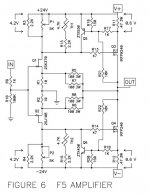
I'm in the process of trying to get my amp to bias properly, doing one channel at a time. but on one of the channels, as soon as i turn the amp on, R14 instantly bursts into flames! i've replaced it twice now, and i cant seem to find the issue, and was hoping someone would have an answer for me. i dont know if i have my trimmers the wrong direction? everywhere i've read, you set it to 0 ohms, and work your way up, monitering voltages across R11 and R12.
maybe i have any of the transistors backwards?
any information will be greatly appreciated,
Thank you early
Cody
But i've run into an issue that i haven't seen yet.
I'm in the process of trying to get my amp to bias properly, doing one channel at a time. but on one of the channels, as soon as i turn the amp on, R14 instantly bursts into flames! i've replaced it twice now, and i cant seem to find the issue, and was hoping someone would have an answer for me. i dont know if i have my trimmers the wrong direction? everywhere i've read, you set it to 0 ohms, and work your way up, monitering voltages across R11 and R12.
maybe i have any of the transistors backwards?
any information will be greatly appreciated,
Thank you early
Cody
my crystal ball is muddy these dayz ( I confess - I'm lazy )........ so - will you enclose some pictures and further info ?
pretty please ........

pretty please ........
R14 is the gate resistor, if P2 is at min resistance, that connects one end of R14 to -V, for current to flow, there must be a fault/short around the IRFP240
When you have found the fault, check that P2 has not been damaged from the current flow before powering up again.
i know i have knock off boards, and would like to apologize to everyone appropriatly. i have great respect for all of you, and at the time of purchasing, didnt even know the amplifier was an F5, and would have absolutely bought the proper one, if i would have realized.
i guess i should have added some more information, although i thought R14 would be important because it arced to the end of its life, twice in a row. I also had R18 burn shortly after it, when i tried firing it up the first time, as well as R1, and R2 turned to a nice golden brown color.
so i replaced all of these resistors, then ran into R14 the second time, and figured i would ask the experts.
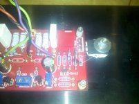
Attachments
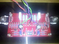
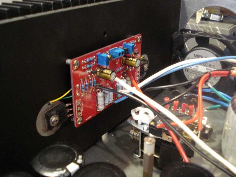
Silly question, I cannot tell from the photo, are there insulators between the FETs and heatsink, and how much clearance is there between the PCB and heatsink, I notice that two of the stand offs are mounted on the FETs and two are on top of the PCB.
Yes, there are insulators. And I believe its close to 1/4 inch standoffs. The reason for the standoffs being on top is because I haven't had time to go get the proper length bolts, being I'm about a half hour from a place that carries that size.
And the capacitors are just on the voltage rails, not anywhere in the actual circuit.
And the capacitors are just on the voltage rails, not anywhere in the actual circuit.
Does that mean he did not get his resistance meter out and check the Vr setting to zero before he powered up?
I checked both sides, and it shouldn't matter what direction they are, that just changes what way you turn the adjuster to move the voltage a specific direction
I checked both sides, and it shouldn't matter what direction they are, that just changes what way you turn the adjuster to move the voltage a specific direction
OK, on PC board 2 pins on rtim pot are conecter -Hmm, OK ... you have 0 ohm before you solder or - after you solder on PCB ?
Looking @ the colors on blown resistors, seems to me - is not 47r, if i compare colors on resistors on another side ..
Just before the very first time you turn it on, the easiest test points to measure are across R3 and R4. Resistance readings should be both zero...
I'll have to double check that. Other then possibly having the POTS wrong, I can't see any issues on the board.
I'm using the Jim's boards, without any problems
They were a gift, and I stuffed them into my amp. It's working fine.
Position of the trim pots isn't vital--as long as you set them for minimum resistance when you first power up the amp....and then set the biases. The way I have my trimpots inserted, the LEFT one is minimum resistance when fully clockwise; the RIGHT one is minimum resistance when fully counterclockwise.....but BE CAREFUL, this is a function of how you inserted the trimpot into the PCB. Best, best thing to do, is to set both pots to minimum resistance using an ohmmeter (or the ohms function on a DMM).
The pic in post #11 is of my amp, but you can't see many details from this photo. I'll be in my home later today, and will grab better pics of one of my Jim's boards, and will post it. I'll also compare your PCB wiring (your pics) to mine.
Did you fully test your power supply for proper rail voltages, before you hooked up the amp PCBs?
Ken
I'll have to double check that. Other then possibly having the POTS wrong, I can't see any issues on the board.
They were a gift, and I stuffed them into my amp. It's working fine.
Position of the trim pots isn't vital--as long as you set them for minimum resistance when you first power up the amp....and then set the biases. The way I have my trimpots inserted, the LEFT one is minimum resistance when fully clockwise; the RIGHT one is minimum resistance when fully counterclockwise.....but BE CAREFUL, this is a function of how you inserted the trimpot into the PCB. Best, best thing to do, is to set both pots to minimum resistance using an ohmmeter (or the ohms function on a DMM).
The pic in post #11 is of my amp, but you can't see many details from this photo. I'll be in my home later today, and will grab better pics of one of my Jim's boards, and will post it. I'll also compare your PCB wiring (your pics) to mine.
Did you fully test your power supply for proper rail voltages, before you hooked up the amp PCBs?
Ken
Actually no, I didn't test my supply voltages. I should have done that as soon as it was together. Will improper voltages make significant differences in setting it up?
- Status
- Not open for further replies.
- Home
- Amplifiers
- Pass Labs
- new f5 bias problem