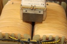
split bobbin means that primary and secondary aren't on top of each other ;
oh, I thought they were 'just' double secondaries, and double primaries 😕
hmm, R-core are airgapped like a double C-core, or 'laminated' ?
another variation could be UI core
Attachments
Hi Rod... I am using your filament supply now with my 45 DHT: that's clearly an improvement over AC supply...
I agree also with Petavgeris : the plastic 220 nF capacitor is a dead end, a good capacitor (I use MKP sprague orange drop) is clearly an improvement . Replacement of R1 by two cheap carbon: again, one step higher. Well , in this tweak session, I give 66% to the capacitor, 33% for the resistor... Next step: Duelund for the resistor, a Jupiter for the capacitor...
Thanks for letting me know! I have a board ready with 2x 1W carbon film resistors. It has succeeded with the testing for stability - and now I must try some listening. Looks like I should get some caps to try, too.
It is always amazing to find how sensitive the filament is to small changes in the power supply & regulation!
Hi Rod
What does the 150n (300B) version do? How critical is its value? And should any replacement have good audio frequency behaviour, or is its the high frequency behaviour paramount? If the latter is so, a superior replacement would necessarily be physically small for optimum performance, ruling out many cap types
Thanks
Paul N
hello Paul, the 150 or 220nF is a compensation capacitor. Actually, its function changed for the v4 design, when some improvements were included. The value can not be altered too drastically in v4 (say,10%).
In addition to audio favourites, the EVOX or Panasonic Stacked Metallized PPS might be worth trying, especially Pana ECHU SMD type, which can be grafted in with some care.
But big lumps, like the lovely Russian FT-2 Teflons, are not recommended, as the physical size must be small.
In addition to audio favourites, the EVOX or Panasonic Stacked Metallized PPS might be worth trying, especially Pana ECHU SMD type, which can be grafted in with some care.
But big lumps, like the lovely Russian FT-2 Teflons, are not recommended, as the physical size must be small.
Hi Rod
I've used Panasonic ECHU (PPS) and ECPU SMD types with great results, as filter or power bypass caps in various DACS, where their high performance/tiny size really pays dividends
I have, I think, 300B v1 boards in my amps (supplied 4/10/10) and v3 boards (supplied 10/5/11) in a friend's. So would 100 - 220n be OK here? Available in EUHU range, but 150n is only available as a ECWU (PEN) type (though I could parallel ECHU caps of course). I'll see what I've got tonight
Paul N
BTW- should I be thinking of upgrading from v1 to v4?! 🙂

Hi
150n 50V ECHU caps are available (my spec sheet must be out of date); Farnell have them- part no. 1855061
Paul N
150n 50V ECHU caps are available (my spec sheet must be out of date); Farnell have them- part no. 1855061
Paul N
Yes, the filament supply is the "nuclear heart" of the DHT, we must never forget it !
For the size of C2, I am experimenting with great result (here a 47nF duelund with a 100nF Sprague). Next time Rod, give us more room on the board !
Never forget! It's great excitement to see that the importance of careful heating is being taken much more seriously here. Thanks!
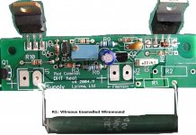
When you like to try big resistors in the R1 position, you can use the alternative mounting used for the 6A transmitters. Here's a pic with the Welwyn W24 in that slot -
.
Attachments
Hi
150n 50V ECHU caps are available (my spec sheet must be out of date); Farnell have them- part no. 1855061
Paul N
Hi Paul,
150 or 220n are fine in the v1 or v3, so please experiment with listening tests....
Hi All
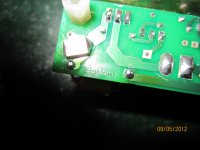
I fitted my 300B supplies with 150n Panasonic ECHU caps, and 4 x 3R3 1W carbon films in parallel, in place of the original 150n polyester caps (I presume) and the 0R83 W/W resistors. I then readjusted the output voltages.
I've had a good listen over the last few days. At first, I wasn't sure I liked the results, but I think this was a case of a need for run in, plus the mod being too revealing for the recordings I chose to play at first. Now I'd highly recommend the changes. You just get more of all the good things SE amps do, already so enhanced by Rod's regulators! Breathtaking (literally in my case) delineation of fine detail in the harmonics of strings- both solo and massed- voices, and wind instruments. Greater depth and solidity of stereo imagery. Just more real!
The caps were a bit tricky to fit, and I ended up putting them on the underside of the board, with the body of the cap running over one the (laquered) tracks connecting to it. One end connects to the underside of one of the unused R2 pads, rather than its original connection point
Paul N
Attachments
Thanks for the report, Paul.
For the 300B range, I have been experimenting with R1 = R2 = 1,5R 1W Carbon film. These fit perfectly in the PCB positions.
The stability has been very good, and their operating temperature is low. I'll be trying them out shortly, for sound, and I am expecting good things!
For the 300B range, I have been experimenting with R1 = R2 = 1,5R 1W Carbon film. These fit perfectly in the PCB positions.
The stability has been very good, and their operating temperature is low. I'll be trying them out shortly, for sound, and I am expecting good things!
Hi Rod
I was a little concerned about long term stability, so I used 4 x 3R3 1W carbon films to spread the load still further. (I didn’t use the R2 mounting points as I’d already soldered the new cap to the rear of one of the pads!) As a rule of thumb, I always like to run resistors at no more than 1/3 their maximum rating. On the other hand, I use a lot modern generic carbon films, and they do seem very stable- and better sounding than their metal film equivalents- despite the theoretical advantages metal films have.
Though, to be honest, I meant to try just the cap change alone to begin with, as I suspect this is the more important factor. But, when it came to it, I couldn’t face the extra hassle of a two step trial!
Paul N
Yes, big margins should be used, especially with wirewounds, as these are designed to operate at high temperatures - 350 deg C for some Vitreous types.
The Regulator's PCB pads & large copper areas are designed to suck heat out of the resistors. Using both R1 & R2 positions aids the effect. The CF 1W run much cooler than WW, with the help of the oversized cooling of the copper-lands. With 1,3A 300Bs they burn ~630mW each. They're rated for 1W at 70 deg C ambient, and with no special care on the PCB layout.
The Regulator's PCB pads & large copper areas are designed to suck heat out of the resistors. Using both R1 & R2 positions aids the effect. The CF 1W run much cooler than WW, with the help of the oversized cooling of the copper-lands. With 1,3A 300Bs they burn ~630mW each. They're rated for 1W at 70 deg C ambient, and with no special care on the PCB layout.
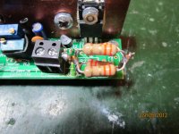
I use now cheap carbon resistor for the filament supply : Yes ! There is clearly an improvement over metal film, by a wide margin !
Let me resume : for R1, carbon, or if no cost object, Duelund.
For C3 (220 nF), anything but the little piece of plastic provided ! (sorry Rod!)
For the other resistors, carbon even the cheapest one !
With those little "tweak" I have the same level of improvement than between let say, a good film capacitor, and , one arm and a leg later, a silver foil Duelund ! 😀
Attachments

OK, please don't laugh, but I have a stupid question. I am not a SS guy and really just learning about tubes. I just got 2 good sized heat sinks for my boards and don't understand how if the transistors need to be electrically isolated they are attached with a metal bolt. I've read that I should use a piece of mica and some kind of goop between the heat sink and the trans. for isolation but then see the metal bolts and it is throwing me off.
Hi All
I fitted my 300B supplies with 150n Panasonic ECHU caps, and 4 x 3R3 1W carbon films in parallel, in place of the original 150n polyester caps (I presume) and the 0R83 W/W resistors. I then readjusted the output voltages.
I've had a good listen over the last few days. At first, I wasn't sure I liked the results, but I think this was a case of a need for run in, plus the mod being too revealing for the recordings I chose to play at first. Now I'd highly recommend the changes. You just get more of all the good things SE amps do, already so enhanced by Rod's regulators! Breathtaking (literally in my case) delineation of fine detail in the harmonics of strings- both solo and massed- voices, and wind instruments. Greater depth and solidity of stereo imagery. Just more real!
The caps were a bit tricky to fit, and I ended up putting them on the underside of the board, with the body of the cap running over one the (laquered) tracks connecting to it. One end connects to the underside of one of the unused R2 pads, rather than its original connection point
Paul N
Hi Paul. I am not sure I understand how a change in components makes a difference in the sound when all they are doing is heating the tube filaments. I am new to this so don't take it the wrong way, I am just trying to learn as much as possible. Cheers, Dennis.
Member
Joined 2009
Paid Member
- Home
- Amplifiers
- Tubes / Valves
- New DHT heater