Good afternoon,
I have a working prototype of a regulator for DHT tubes. This is a voltage controled current source, so it is in no way in the audio path, similar to the tentlabs and coleman modules.
The tenative specs are as follows:
Minimum input voltage : 9VDC
Maximum input voltage : 30VDC
Output adjust range: 5.0-30V by means of a 25t pot.
Rated current : 1-10A
Peak current during warmup : 20A
Noise at Rated output current : Less than 1mV measured using a HP benchmeter.
Dropout voltage: About 3V at rated current.
Output devices: Two TO247 mosfets rated for 350W DC duty with an infinite heatsink. In reality these can dissipate about 40-50W on a heatsink under 1K/W.
I am now thinking about a redesign of my prototype to include some different features, and order a 70uM PCB instead of the standard 35uM, and perhaps even include pressfit screw connectors for the PCB.
I know its a small number of Diyers working with tubes that use THIS much curret. However how sensible would a DC regulator for tubes like the 833 Be? And is there anyone interested in the project?
I dont build with anything like these tubes, ive shipped some boards to some friends for use with some transmitter tubes. And to put it blunt further development needs to make good on my time.
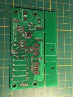
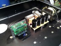
A picture of a prototype board is attached. You are to use the board to mark out the holes on the heatsink, and then break of the part above the FETS.
I have a working prototype of a regulator for DHT tubes. This is a voltage controled current source, so it is in no way in the audio path, similar to the tentlabs and coleman modules.
The tenative specs are as follows:
Minimum input voltage : 9VDC
Maximum input voltage : 30VDC
Output adjust range: 5.0-30V by means of a 25t pot.
Rated current : 1-10A
Peak current during warmup : 20A
Noise at Rated output current : Less than 1mV measured using a HP benchmeter.
Dropout voltage: About 3V at rated current.
Output devices: Two TO247 mosfets rated for 350W DC duty with an infinite heatsink. In reality these can dissipate about 40-50W on a heatsink under 1K/W.
I am now thinking about a redesign of my prototype to include some different features, and order a 70uM PCB instead of the standard 35uM, and perhaps even include pressfit screw connectors for the PCB.
I know its a small number of Diyers working with tubes that use THIS much curret. However how sensible would a DC regulator for tubes like the 833 Be? And is there anyone interested in the project?
I dont build with anything like these tubes, ive shipped some boards to some friends for use with some transmitter tubes. And to put it blunt further development needs to make good on my time.
A picture of a prototype board is attached. You are to use the board to mark out the holes on the heatsink, and then break of the part above the FETS.
Attachments
Last edited:
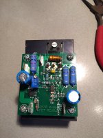
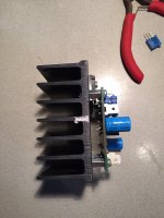
Here are some more pictures of the smaller version, intended for GM70 ect. Current capability is in the ballpark of 5A continuous.
The heatsink is 2.3K/W and is capable of feeding a GM70 from a 20VAC rectified winding.
The heatsink is 2.3K/W and is capable of feeding a GM70 from a 20VAC rectified winding.
Attachments

Cool project! To heat 833s, I found that the Meanwell LRS-200-12 turned all the way down was a really simple solution.
What you have here looks to be way smaller (although you'd still need a PT, rectifier, and filter caps), and the noise specs are far better.
What you have here looks to be way smaller (although you'd still need a PT, rectifier, and filter caps), and the noise specs are far better.

Both Are interesting approaches, I have a friend who is currently building with the boards for the 10A version.
One thing to note about my circuit: it can supply higher current than the rated current for particular tubes. This is because tube heater can be out of spec current wise +-10% for some examples.
In other words : You can SET the surge current during warm up, in that way the loop will run into the clamp voltage set by a zener. And the CCS wont be able to increase current further.
The maximum current is dependant on the zener voltage used in the control loop, and the value of the measuring resistors.
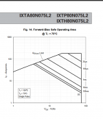
One very nice aspect about my build, is that the used L2 series mosfets have VERY wide DC SOA characteristics. unless you manage to get the heatsink up to 80C those Fets are unlikely to fail.
PN on my build is IXTH80N075L2 see the attached SOA curves on that device.
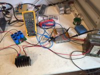
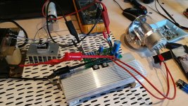
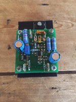
Also attached: A photo by a friend of mine, he is testing the modules for me, the tube in question is a 7.5A 5V tube.
Right now i have 4 boards left i think, any takers? the circuit is relatively mature. but YMMV .
One thing to note about my circuit: it can supply higher current than the rated current for particular tubes. This is because tube heater can be out of spec current wise +-10% for some examples.
In other words : You can SET the surge current during warm up, in that way the loop will run into the clamp voltage set by a zener. And the CCS wont be able to increase current further.
The maximum current is dependant on the zener voltage used in the control loop, and the value of the measuring resistors.
One very nice aspect about my build, is that the used L2 series mosfets have VERY wide DC SOA characteristics. unless you manage to get the heatsink up to 80C those Fets are unlikely to fail.
PN on my build is IXTH80N075L2 see the attached SOA curves on that device.
Also attached: A photo by a friend of mine, he is testing the modules for me, the tube in question is a 7.5A 5V tube.
Right now i have 4 boards left i think, any takers? the circuit is relatively mature. but YMMV .
Attachments
I could build a version using a single FET built for 10A continuous, from my friend i understood that the double FET version is higher noise then the single Fet versions he tested. Why that is i will try to understand later when i have the time.
Perhaps i could decrease dropout to about 1-1.5V in that case the transistor would dissipate about 25W 13V in 10V out. and 38W in high mains conditions,
Decreasing the dropout would entail poorer CCS performance because the mosfet is working at the unlinear part of the curves, so the opamp needs to work harder to keep the CCS working as expected.
Coincidentially 13V is about the expected load voltage from a 12V toroid using normal rectification and 33000uF+
Perhaps i could build a version with three Mosfets and a 100mOhm TO220 sense resistor. that would allow dropout voltages of 10V at 10A safely. And i could rework the driver to be able to use a more stable opamp like the LM358 This would entail using LH0002 driver for the FET''s. cause the 358's will scream if you load them with this much miller capacitance. 🙁
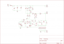
I've just slightly reworked the first prototype boards, it should be a lot lower noise now, but i wont know untill i build some.
It has to do with the opamp, ive placed a cap at the output to decrease the slew rate of the opamp, so it cannot respond to HF on the input or from ambient, to keep the thing stable, this cap needs to be chosen so that the opamp still has a slew rate of at least 1V/1mS
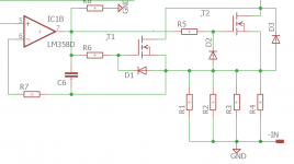
Attached the schematics for the CCS, the opamp is claimed to be stable with unlimited capacitive loads, im thinking 10uF for C6 .
Anyone wants to chime in for boards ? Two boards are €10 total.
It has to do with the opamp, ive placed a cap at the output to decrease the slew rate of the opamp, so it cannot respond to HF on the input or from ambient, to keep the thing stable, this cap needs to be chosen so that the opamp still has a slew rate of at least 1V/1mS
Attached the schematics for the CCS, the opamp is claimed to be stable with unlimited capacitive loads, im thinking 10uF for C6 .
Anyone wants to chime in for boards ? Two boards are €10 total.
Attachments
I've just slightly reworked the first prototype boards, it should be a lot lower noise now, but i wont know untill i build some.
It has to do with the opamp, ive placed a cap at the output to decrease the slew rate of the opamp, so it cannot respond to HF on the input or from ambient, to keep the thing stable, this cap needs to be chosen so that the opamp still has a slew rate of at least 1V/1mS
Attached the schematics for the CCS, the opamp is claimed to be stable with unlimited capacitive loads, im thinking 10uF for C6 .
Anyone wants to chime in for boards ? Two boards are €10 total.
Yes - interested in boards for my 833A project, as a matter of fact, I'll likely buy two sets. Please private mail me with full schematic and parts list.
Cheers,
Reply Send,
If anyone else is interested, dont hesitate to contact me. The suggested price of €5 per board is the group buy price, and includes the schematic once the boards become available. I got all the parts for the module stocked except the FET's. I am quite hesitant to provide the correct schematic right now, fruits of my labor and all.
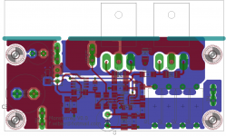
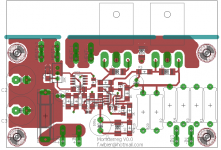
Here is the board with some changes implemented, the board grew in size by 10mm but i added a fuse holder, and two extra current measurement resistors. With 6X 470mOhm current measurement resistors the cold current is 12.8A +-10% so i might have to stock up on 390mOhm or 330mOhm.
See attached the plot of the board. 52x100mm is the complete area.
If anyone else is interested, dont hesitate to contact me. The suggested price of €5 per board is the group buy price, and includes the schematic once the boards become available. I got all the parts for the module stocked except the FET's. I am quite hesitant to provide the correct schematic right now, fruits of my labor and all.
Here is the board with some changes implemented, the board grew in size by 10mm but i added a fuse holder, and two extra current measurement resistors. With 6X 470mOhm current measurement resistors the cold current is 12.8A +-10% so i might have to stock up on 390mOhm or 330mOhm.
See attached the plot of the board. 52x100mm is the complete area.
Attachments
Last edited:
Parallel Coleman regulators on the heat sink during the 833 amp build.
Hi! The heatsink looks rather small considering the application. Is it helped by the fan that cools the 833?
That whit the MK1 eyeball it looks to be a .5K/W heatsink with some extra cooling provided by the top plate. Coleman runs at what? 6V dropout ?
Heatsink temperature would be ~50C in my calculations, die temperature on the transistors significantly higher because the 2SC6144 is a plastic package.
Im surprised it appearantly works for 5 years now.
Heatsink temperature would be ~50C in my calculations, die temperature on the transistors significantly higher because the 2SC6144 is a plastic package.
Im surprised it appearantly works for 5 years now.
Im surprised it appearantly works for 5 years now.
You are confusing my regulator with something has not actually been designed to a professional standard (industrial, PC, Radio and EMC are among my day jobs). Not to mention that my filament regulator has 10 years of track record in a Wordwide field.
The voltage drop AND the current in the TO220-FP-packaged transistor are both fully controlled in the Coleman regulator.
In the case of the 833C design, the maximum power dissipated - even with +10% high mains, and +10% adjusted current, is 8.3W. This is maintained even at a cold start. If the heatsink does reach 50°C, the maximum allowable power for that component at Tc=60°C is 18W - thus we have more than 50% margin on that measure.
My work is always designed - and thoroughly tested - before being made available to others.
Let the buyer beware of any designs that are sold before such work takes place.
Hi! The heatsink looks rather small considering the application. Is it helped by the fan that cools the 833?
No problem at all with cooling. The large Al heat spreader block is fastened to the Al top plate with thermal paste, and the heat sink is in the path of the airflow from the vents at the back of the amp to the fan under the 833C. It all works well because the heat drawn from the inside of the amp preheats the air that flows past the 833C; this tube needs to run hot, and overcooling is to be avoided. Many radio transmitters use cooling air preheated by the rest of the electronics for that reason.
Last edited:
You are confusing my regulator with something has not actually been designed to a professional standard (industrial, PC, Radio and EMC are among my day jobs). Not to mention that my filament regulator has 10 years of track record in a Wordwide field.
The voltage drop AND the current in the TO220-FP-packaged transistor are both fully controlled in the Coleman regulator.
In the case of the 833C design, the maximum power dissipated - even with +10% high mains, and +10% adjusted current, is 8.3W. This is maintained even at a cold start. If the heatsink does reach 50°C, the maximum allowable power for that component at Tc=60°C is 18W - thus we have more than 50% margin on that measure.
My work is always designed - and thoroughly tested - before being made available to others.
Let the buyer beware of any designs that are sold before such work takes place.
You Are right in regards to the TO-220FP packages being able to handle the power. I forgot they lack the thermal resistance from a silpad/mica and grease.
Im no engineer, and this product is the product of mostly my hobby, I didnt intend to step on any toes. I usually derate to 25% of spec, hence note that this supply uses two mosfets where one would have sufficed.
I'm not really helpful by not posting the schematic in a public place anyway. I was afraid someone might run with it. But a friend of mine explained the peculiarities of the patent system with prior art and all.
See the attached schematic and judge for yourself. It seems to be stable now ive done some modifications, first i had problems with the opamp producing harmonics that caused instabilites, that caused the system to oscillate at about 300Khz. But a small capacitor from gate to source fixed that. I think it is because i swamped the miller capacitance and decreased the possible dV/dT on the gate of the fet.
The opamp ofcourse is no 358 its in fact a LM7322
I havent run any phase response simulations on the system, i welcome anyone to do so, if you want to I will PM a complete list of the used critical parts.
Attachments
Last edited:
...and just like clockwork, somebody has to come in here and trash the commendable efforts of a hobbyist - in order to promote his commercial product offering. I'm getting pretty sick of this, to be honest.
This is supposed to be a DIY hobbyist forum, not a place to promote commercial sales. There is a vendor's forum for that, I believe.
This is supposed to be a DIY hobbyist forum, not a place to promote commercial sales. There is a vendor's forum for that, I believe.
Oh well, to be fair the complete story is different.
In all openness i PMed Rob saying i made something similar to one of his product and offered to sell the entire project to him "For a couple 100 quid" So i could move on the the next project. Never got a reply.
The circuit is is no means mature, but it shows potential, if the RC time is chosen right the startup is good with little overshoot. The mosfet is rugged, and i think i fixed the instability in the constant current part (presumably the hardest part of the circuit)
The circuit shown above, has some extra parts that can be done away with, and it will work, as a matter of fact i have a module here on my desk that works. with no oscillation.
Attachments


Last edited:
...and just like clockwork, somebody has to come in here and trash the commendable efforts of a hobbyist - in order to promote his commercial product offering. I'm getting pretty sick of this, to be honest.
This is supposed to be a DIY hobbyist forum, not a place to promote commercial sales. There is a vendor's forum for that, I believe.
Actually, I was responding to an instance of questioning the reliability of my filament regulator (in post 12).
Last edited:
Congratulations, V4lveLover - I think you have a winner in that circuit. It's nice to see different approaches to the same problem. And THANK YOU for sharing it with the DIY community.
There is also a recent article on DHT heating in the blog Tubecad.com. John Broskie, the author - has come up with a number of different and very effective approaches, all of which he freely shares with the DIY community. Broskie is a very intelligent and prolific engineer - you should go over there and search for his recent DHT heating article. It is excellent reading, and quite informative.
Regards,
Exactly. And Rod provides endless assistance to dummies like me.Actually, I was responding to an instance of questioning the reliability of my filament regulator (in post 12).
- Home
- Amplifiers
- Tubes / Valves
- New DHT heater, any need for a 10A+ version?