Hi, I decided to start my new ClassD project.
It will work for bass only,20Hz-200Hz
Oscillator with 4 Mhz ceramic resonator, MC14060BCP oscillator and divider, on pin 5 exactly 100Khz.
Here is some pictures of trianglegen output, measured wth a 20 Mhz scope
On pin 5 output:
On trianglegen output:
Is this correct?
It will work for bass only,20Hz-200Hz
Oscillator with 4 Mhz ceramic resonator, MC14060BCP oscillator and divider, on pin 5 exactly 100Khz.
Here is some pictures of trianglegen output, measured wth a 20 Mhz scope
On pin 5 output:
An externally hosted image should be here but it was not working when we last tested it.
On trianglegen output:
An externally hosted image should be here but it was not working when we last tested it.
Is this correct?
I
Being enthusiasmed, I forgot to mount the operational on soket
Now, on output, the signal is like this:
The schematic is that:
Any opinions?
Suggestions?
Being enthusiasmed, I forgot to mount the operational on soket
Now, on output, the signal is like this:
An externally hosted image should be here but it was not working when we last tested it.
The schematic is that:
An externally hosted image should be here but it was not working when we last tested it.
Any opinions?
Suggestions?
Well, so far so good... but generating a triangle wave is straightforward. What you'll see around here is mostly kits and one-chip wonder solutions because it can get hairy further down the rest of the chain. What will be really interesting is what you come up with for a dead-time generator, and how you couple the gate driver circuits from the low-level PWM signal into the bank of hexfets.
I'm looking at class D architectures for bass as well. Starting with the output H-bridge, with optically-isolated gate drive (like Crown CE4000, but I'm not doing BCA). Once I nail down how fast this thing can reliably switch, that will determine what kind of dead time and carrier frequency it can handle.
I'm looking at class D architectures for bass as well. Starting with the output H-bridge, with optically-isolated gate drive (like Crown CE4000, but I'm not doing BCA). Once I nail down how fast this thing can reliably switch, that will determine what kind of dead time and carrier frequency it can handle.
Excuse
Excuse me, at output triangle gen and oscillator, is 125Khz, not 100, how I wrote and put on schematic(I was thinking at something else ...)
On LM361 outputs, I obtained those signals:
Excuse me, at output triangle gen and oscillator, is 125Khz, not 100, how I wrote and put on schematic(I was thinking at something else ...)
On LM361 outputs, I obtained those signals:
An externally hosted image should be here but it was not working when we last tested it.
100kHz... 125kHz... what's the difference?😉 I just figured your scope was out of calibration.....
wg_ski said:100kHz... 125kHz... what's the difference?😉 I just figured your scope was out of calibration.....
With 4 Mhz Crystal, you will obtain 125 Khz divided, not 100 Khz, my blame for thinking at other things whan I wrote...
Possible the scope being decalibrate...
I will check.
I'm back
I'm back, it's a full bridge configuration, it works😉 !
For 125 Khz switching, how many uH must have the output coils ?
I tried with 80uH for low side, also for Hi side too, and everything is COLD.
No coils warming up and no mosfets too, in IDLE, they rest around 35-40 celsius degrees maximum, and around 55 degrees in load, delivering 33Volts RMS on 4 ohms load, with 56 volts supply.
I will come later with some screens.
Some
Some pictures and movies.
It works perfectly at 125Khz, I have an output , only 130 milivolts residual of 125Khz switching freq.
Supplied at +/- 30Vcc, it gives around 350Watts on 4 ohm, with more than 90% randament.
All is in studying stage, following improvements.
Is done with P and N mosfets, on output, next modification is to use only N mosfets.
Any sugestions?
Triunghi:
(links removed by mod due to their inappropriate content.)
Also
Also, first movie, I put again, because first link was bad...
(link removed by mod for inappropriate content)
Excuse support of the site(litlle nasty),and download it.
Also, first movie, I put again, because first link was bad...
(link removed by mod for inappropriate content)
Excuse support of the site(litlle nasty),and download it.
+/- 30 volts power supply??
That should give no more than about 20 V RMS, which is 100 watts / 4 0hm.
Am I missing something here?
Pieter
That should give no more than about 20 V RMS, which is 100 watts / 4 0hm.
Am I missing something here?
Pieter
pieter t said:+/- 30 volts power supply??
That should give no more than about 20 V RMS, which is 100 watts / 4 0hm.
Am I missing something here?
Pieter
Full bridge.
DjLeco!
For 125 Khz switching, how many uH must have the output coils ?
For 4 ohm full bridge I wouldn't use more then 20 uH, but then it have to be a low-loss type (gapped ferrite with litze, low-mu MPP iron powder, etc...). There are no strict rules, you have to balance between price, size, quality, etc...
I tried with 80uH for low side, also for Hi side too, and everything is COLD.
With such a big heatsink it's not a mistery! 🙂
BTW, terminology: the inductors are not separated for "high side" and "low side". They are on the left and right (inverting and non-inverting, A and B, etc...) legs, or outputs!
Any sugestions?
If you don't need higher supply voltage, you could use 100 V mosfets, with lower losses.
IMO it's a waste of time and money to build such a complicated triangle generator, and all the other things on double sided PCB. With a very simple triangle generator, and with feedback you can reach better result for much lower price.
Attachments
Re: I'm back
Cold? 55C seems a little warm. I wonder how much cross conduction you get with that rat's nest. Not that it will be a problem or blow up at this relatively low power level, but I bet it can be improved and truly run cold.
DjLeco said:
I tried with 80uH for low side, also for Hi side too, and everything is COLD.
No coils warming up and no mosfets too, in IDLE, they rest around 35-40 celsius degrees maximum, and around 55 degrees in load, delivering 33Volts RMS on 4 ohms load, with 56 volts supply.
Cold? 55C seems a little warm. I wonder how much cross conduction you get with that rat's nest. Not that it will be a problem or blow up at this relatively low power level, but I bet it can be improved and truly run cold.
The cause of 55C is probably the high Rdson of the SFH9154 (0,2 ohm), but 35-40 celsius with an ambient temp of 20C is also too high, and this really can be caused by some cross-conduction, since inductor current is negligible.
DjLeco!
You should measure idle supply current. If it's more then 50 mA, then you can improve it further. 15 mA is achieveable with properly selected FETs, inductors, etc...
DjLeco!
You should measure idle supply current. If it's more then 50 mA, then you can improve it further. 15 mA is achieveable with properly selected FETs, inductors, etc...
Yes
Yes, but the amp is not intended to use at low voltages.
What you have seen is just a small test functonality.
I don't want to use any of IRS circuits, I prefear discrete
components, wich will offer me more versatility and modifications
options, instead IRS wich have his alot of problems, and no more versatility.
My schematic are now in fullbridge, but oficially it uses P and N MosFets on output stage, drived by discrete transistors, wich are deadtime included in it.
I want to modify it to use only N Mos, MosFets on output stage, in fullbridge too, but I'm not sure exactly how to do this, and what kind of Low Side and High Side drivers IC's to use ...
Any sugestion(s) will be appreciate.
Refering at output coils, I have some cores R50 iron powder from Gendalex (England) coded G1W 88 S540 wich I'm 100% sure is made from Iron Powder, and is sure suitable for output coils.
Regarding 20uH output inductance used on 500Khz switching amp from Crown (K series BCA amplifier) , I determined to use around 80uH for 125 Khz switching freq.
Is OK to have a total residual output of 130 milivolts 125 Khz on bridged output after the coils?
Any other opinions for output coils inductance will be appreciate, just for 125 Khz switching freq,no more, no less.
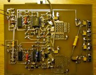
Some pictures and general schematic of Hi Speed comparator and output stage that I have used:
And coil that I have used (the blue one), comparing to an R63 ferrite (the gray one) and an a small R25 iron powder that is used on PC power supplies (the yellow one).
I have measured the around 40 degrees after couple minutes of testing, I was write wrong...
Oficial in idle, the heatsink is cold like room temperature,I tested that after 1 hour of idle of the amp.
And the temperature is measured by hand touching, approximate, not real...
Excuse for PORN on that uploading site, Is the fastest for me in Romania, instead others...
Sorry bout' that, just ignore it and download the movies...
Yes, but the amp is not intended to use at low voltages.
What you have seen is just a small test functonality.
I don't want to use any of IRS circuits, I prefear discrete
components, wich will offer me more versatility and modifications
options, instead IRS wich have his alot of problems, and no more versatility.
My schematic are now in fullbridge, but oficially it uses P and N MosFets on output stage, drived by discrete transistors, wich are deadtime included in it.
I want to modify it to use only N Mos, MosFets on output stage, in fullbridge too, but I'm not sure exactly how to do this, and what kind of Low Side and High Side drivers IC's to use ...
Any sugestion(s) will be appreciate.
Refering at output coils, I have some cores R50 iron powder from Gendalex (England) coded G1W 88 S540 wich I'm 100% sure is made from Iron Powder, and is sure suitable for output coils.
Regarding 20uH output inductance used on 500Khz switching amp from Crown (K series BCA amplifier) , I determined to use around 80uH for 125 Khz switching freq.
Is OK to have a total residual output of 130 milivolts 125 Khz on bridged output after the coils?
Any other opinions for output coils inductance will be appreciate, just for 125 Khz switching freq,no more, no less.
Some pictures and general schematic of Hi Speed comparator and output stage that I have used:
An externally hosted image should be here but it was not working when we last tested it.
And coil that I have used (the blue one), comparing to an R63 ferrite (the gray one) and an a small R25 iron powder that is used on PC power supplies (the yellow one).
An externally hosted image should be here but it was not working when we last tested it.
An externally hosted image should be here but it was not working when we last tested it.
An externally hosted image should be here but it was not working when we last tested it.
Pafi said:The cause of 55C is probably the high Rdson of the SFH9154 (0,2 ohm), but 35-40 celsius with an ambient temp of 20C is also too high, and this really can be caused by some cross-conduction, since inductor current is negligible.
DjLeco!
You should measure idle supply current. If it's more then 50 mA, then you can improve it further. 15 mA is achieveable with properly selected FETs, inductors, etc...
I have measured the around 40 degrees after couple minutes of testing, I was write wrong...
Oficial in idle, the heatsink is cold like room temperature,I tested that after 1 hour of idle of the amp.
And the temperature is measured by hand touching, approximate, not real...
Excuse for PORN on that uploading site, Is the fastest for me in Romania, instead others...
Sorry bout' that, just ignore it and download the movies...
I'm sorry but using these sides for uploading "because it is fastest" is no reason.
You are crossing the line here.
When I am home, surfing DIYaudio and kits are in the home too, I just don't expect, and want, these images on my screen.
Please use another site for uploading.
Pieter
You are crossing the line here.
When I am home, surfing DIYaudio and kits are in the home too, I just don't expect, and want, these images on my screen.
Please use another site for uploading.
Pieter
pieter, that's why you report a post. Please do so in the future. I have dealt with the offending links.
pieter t said:I'm sorry but using these sides for uploading "because it is fastest" is no reason.
You are crossing the line here.
When I am home, surfing DIYaudio and kits are in the home too, I just don't expect, and want, these images on my screen.
Please use another site for uploading.
Pieter
Sorry for disturbing you with my upload links, I'm not allowed to edit my post(s) just for 30 minutes from posting.
I please an admin to DELETE the movie links, and that's it.
No problem for me, sorry for ofending you.
No need to argue or contradictory posts, but that site allows me to upload with around 1-3 Mb/sec (I'm owner of 50 Mb/ sec internal connection), others external connection just couple Kb/sec, not my blame...
I will try to upload on tinypic...
I have some cores R50 iron powder from Gendalex (England) coded G1W 88 S540 wich I'm 100% sure is made from Iron Powder, and is sure suitable for output coils.
Iron powder cores have an incredibly wide variety. For example the yellow-white color-coded (micrometals type -26) core is an iron-powder core also, but it has very high loss, it's almost unusable for amplifier, but it's good for output coil of an SMPS. I don't know Gendalex cores. Use it, if you want!
Regarding 20uH output inductance used on 500Khz switching amp from Crown (K series BCA amplifier) , I determined to use around 80uH for 125 Khz switching freq.
Actually the FETs of K1 and K2 amps work at 250 kHz. Furthermore a BCA amp works quite differently, and generally optimal output inductance is not exactly reversely proportional to fsw. Use the value what you insist, but then don't ask for advice, please!
I want to modify it to use only N Mos, MosFets on output stage, in fullbridge too, but I'm not sure exactly how to do this, and what kind of Low Side and High Side drivers IC's to use ...
What could I say? I would suggest IR2xxx, but you've already discarded them.
Is OK to have a total residual output of 130 milivolts 125 Khz on bridged output after the coils?
There is no rule for optimal residual. 130 mV alone is OK.
that site allows me to upload with around 1-3 Mb/sec
And it allowed me to download with 5 kB/sec... At least you could edit it to be a little less gigantic (400MB ?!?
 ). Don't waste other people's time!
- Status
- Not open for further replies.
- Home
- Amplifiers
- Class D
- New ClassD project Starting from 0