
Better connect the 0,47µF to the anode of the triode 😱
Pour le reste,bon amusement 🙂
Mona
hello ,
Young error on the plan, j put the resistance before the capacity and c is l opposite!
thank 😉
You do realize that an EL508/PL508 is intended for the field deflection output stage of a color TV and as such may not be the most linear tube available. The datasheet doesn't even show I(a)/V(g) graph, whereas the EL84 does. Maybe better use an EL503 if you can get it. Compare with PL504 (line output) which does have this graph.
But then again, why not give it a go...
But then again, why not give it a go...
I built a SE whit the PL508, Better use Screen drive for it. the first grid is very un-lineair . yet if you manipulate the potential on G2 it shows quite a lineair relation between vg2 and IA
If you are serious about building this amp. I could wire up my test setup and give you some curves VG2/IA whit G1 tied to cathode.
V4lve.
If you are serious about building this amp. I could wire up my test setup and give you some curves VG2/IA whit G1 tied to cathode.
V4lve.
hello ,
J have to use doc so joined, the tube seems etre well also in the audio only one, but doc does not say granf thing, I know just that the tube EL-PL 508 has a cousin 6P41S!
J like the assemblies which are not common.
PL508 @ The National Valve Museum
thank for me help 😉
J have to use doc so joined, the tube seems etre well also in the audio only one, but doc does not say granf thing, I know just that the tube EL-PL 508 has a cousin 6P41S!
J like the assemblies which are not common.
PL508 @ The National Valve Museum
thank for me help 😉
Some of the curves can be found using the following link:
http://frank.yueksel.org/sheets/010/p/PL508.pdf
But I agree with v4lve lover to say that it will probably behave far better if screen grid driven.
http://frank.yueksel.org/sheets/010/p/PL508.pdf
But I agree with v4lve lover to say that it will probably behave far better if screen grid driven.
hello ,
sur la doc de base , il est mis qu a 190 V= anode , on as 60 mA , ca équivaut a 11.5 W PA .
j ai donc calculer un TRS pour cette valeur :
190 Va / 60 mA = 3166.66 soit 3.2 Kohms pour un TRS en SE ; un TRS de 5 Kohms me semble bien si je reste dans cette plage de tension !
j ai pas trouver la doc des 6p41s , elle doit surment afficher des valeurs intéressantes .
désoler , j ai pas traduit en mode anglais !
merci bien 😉
Tube datas from 6p41s (6п41с) can be found through the following link
''Èñòîê2''. Ðàäèîëàìïû - ïî÷òîé. Ïàðàìåòðû è õàðàêòåðèñòèêè 6Ï41Ñ
I can help you for translation if you need it.
But try not to use french on this forum, or directly ask your questions on a french one.
I guess this can be frustrating for other members.
In case of necessity, you'll find a mail link (contact) at the end of the first page, on my web site.
hello ,
J use l English partially, I am not tres hardly meme in radio...
J like the assemblies exotic because tres few to use and so too easy for assemblies normalized(standardized) in audio, as a result, j uses with my stock of recovery(recycling).
Thank you for your help
😉
J use l English partially, I am not tres hardly meme in radio...
J like the assemblies exotic because tres few to use and so too easy for assemblies normalized(standardized) in audio, as a result, j uses with my stock of recovery(recycling).
Thank you for your help
😉
Jean Michel, try this french forum.
It's held by a Ham (F6BNY) and you'll find many answers to questions you haven"t asked yet.😀
Audiyofan.org • Page d?index
It's held by a Ham (F6BNY) and you'll find many answers to questions you haven"t asked yet.😀
Audiyofan.org • Page d?index
I'm having issues measuring this tube on my valve meter due to excessive HF oscillations .
So I connected an old rats nest experiment on my bench. It works very well , but needs some NFB to clean up the Bass. Witch isn't all to loud.
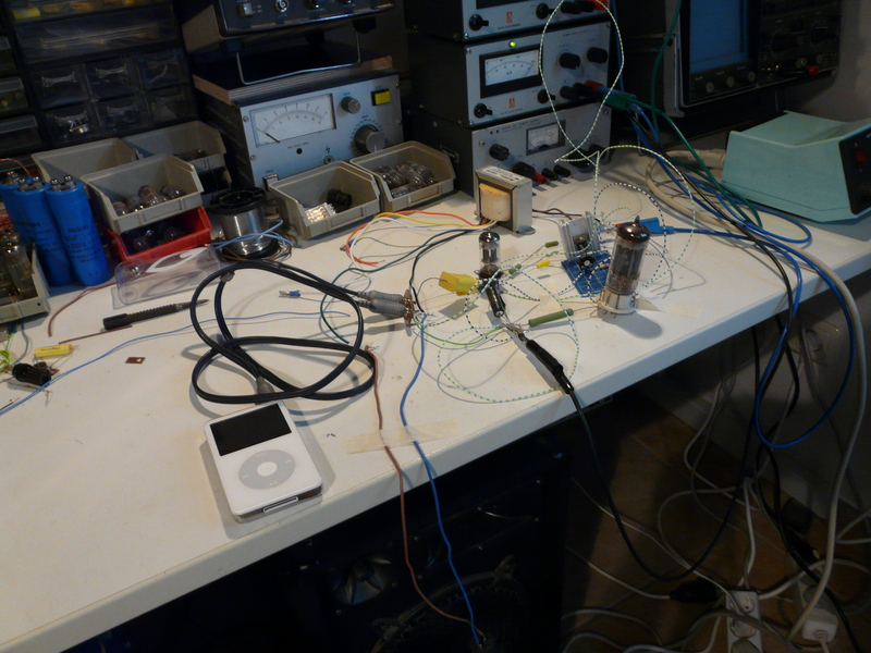
I found out about 80-100 volt swing is needed to fully drive the tube. at 300 volt anode voltage.
The tube conducts 5mA whit VG2=0 volt and 100mA @ 60 volt VG2
Im thinking of using an Opamp Class A shunt element whit a BJT to drive this tube. that way you could drive the amp directly from A CD player. but most of you would disagree.
By the way, this tube seems to cope very well whit 30Watt PD 😀
V4lve
So I connected an old rats nest experiment on my bench. It works very well , but needs some NFB to clean up the Bass. Witch isn't all to loud.
I found out about 80-100 volt swing is needed to fully drive the tube. at 300 volt anode voltage.
The tube conducts 5mA whit VG2=0 volt and 100mA @ 60 volt VG2
Im thinking of using an Opamp Class A shunt element whit a BJT to drive this tube. that way you could drive the amp directly from A CD player. but most of you would disagree.
By the way, this tube seems to cope very well whit 30Watt PD 😀
V4lve
Damned!
I just come to see that you're already registered on this forum... 😱
😀 hehehehe , not problem , so good forum for help and new build audio

bye , good day 😉
I found out about 80-100 volt swing is needed to fully drive the tube. at 300 volt anode voltage.
The tube conducts 5mA whit VG2=0 volt and 100mA @ 60 volt VG2
An SRPP of 6SN7 would esily drive your screen grid.
It's worth a trial...😉
Here I am again, j have so much to go(take) up d antenna(office) with a lot of plan diverse, whom j have to forget full of things which j liked and in particular, tubes BF and HF, as a result, I go(take) up little n matter what, I am almost crazy...
me old call is FA1PZN , me new call is F4PZN , only qrv to 12 meter , 10 meter and 2 meter , so 6 meter is stopped for not antenna .
😛
me old call is FA1PZN , me new call is F4PZN , only qrv to 12 meter , 10 meter and 2 meter , so 6 meter is stopped for not antenna .
😛
- Status
- Not open for further replies.
- Home
- Amplifiers
- Tubes / Valves
- new build SE to EL 508