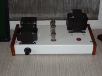
Close to 7 years ago I built the "Budgy" from Shannon Parks (diytube dot com) and was satisfied with the results. In a moment of delusion I sold the amplifier to fund building an Audio Note kit 4 clone. (PP 6V6).
Not happy with the Audio Note I sold it and am now collecting parts for a new SE 6BQ5.
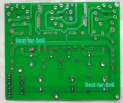
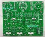
No longer is the Budgie PCB available and rather than going through a steep learning curve with software to make my own PCB I searched on ePray and found a PCB that looked like it could be used.
It is using the 5670 / 2C51 / 6N3P as a driver and headphone addicts seem to like that tube and also it has found its way into DAC's. It is also used in the El Cheapo amp. Plenty available NOS.
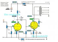
When the PCB arrived earlier this week it was slightly different from advertised, it was missing two tracks and used on the 6BQ5 the pins 1, 6 & 8 as tie points (a no-no). Some older NOS EL84 use some of those pins, so does the 7189A and there can be fireworks when inserting a tube that has used one of these pins.
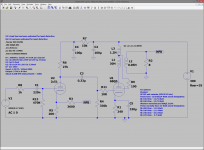
The values shown on the PCB wer different from the values in the schematic and I had to model it in LtSpice as the vendor was unhelpfull. Did not take me long to get familiar again with LtSpice after not using it for over 10 years.
Loadlines for the 5670 seemed a tad strange too and I found a website where I could model the triodes. (Triode / Pentode Loadline Simulator v.1.0 (20161216 [url]www.trioda.com)[/url])
Mullard in the UK originally specified a 20% ~ 22.5% tap for distributed load and I'll be using that instead of the common 43%. Transformers have been ordered.
Mains transformer will be 240V @ 240mA with bridge rectification and CLC.
Eli Duttman has been raving on about "hash filters" so those will be included.
The TDK 2CP2511 (that has excellent tracking) will be used for volume. There will be some high value and appropriate current rating NTC resistors on the primary which will prevent the filaments lighting up like a light bulb. The NTC's will keep B+ below 300V (filaments draw current dropping the voltage across the primary) and after 60 seconds an Amperite delay relay will short the NTC resistors out of the circuit.
Still undecided on the tube sockets - I searched the web and found that some builders of guitar amps use chassis mounted tube sockets as their experience with PCB based sockets has been less than optimal (cracked copper tracks due to the heat or solder melting) The 7189A can run hot.... (especially the way the guitar players bias them). I am leaning towards using under chassis sockets and soldering nuts to the socket so I can remove them without having access to the back. There will be some stopping resistors going to the socket (and a few ferrite beads).
The circuit orginally used a 220 Ohm resistor but it is in the middle of he PCB and produces a bit of heat so was not too happy with it besides it results in about 240mV ripple which is audible in sensitive speakers. A choke will be used instead.
Not yet decided on the choke I'm going to use, I'm thinking about the 6H Triad Magnetics or the 1.5H Hammond. The 6H will have about 17mV ripple at B+ to the power tubes, the 1.5H works out at about 77mV.
I am attaching the pictures on the original schematic as advertised, the photo's of the PCB and the modelling in LtSpice.
Any suggestions for improvement are appreciated but I am stuck using this PCB (I really do not feel like redoing the PCB). I also will stick to the selection of tubes as the first ones of them have started to arrive.
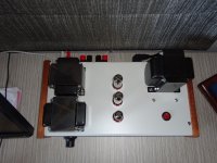
Pictures of my previous build are attached too but I'm going to try to make it smaller this time so it takes up less space on my desk.
Looking forward to suggestions before I start working on a chassis. Hopefully your input helps with avoiding having to start all over again - I'll appreciate a sanity check. Thanks!
Not happy with the Audio Note I sold it and am now collecting parts for a new SE 6BQ5.
No longer is the Budgie PCB available and rather than going through a steep learning curve with software to make my own PCB I searched on ePray and found a PCB that looked like it could be used.
It is using the 5670 / 2C51 / 6N3P as a driver and headphone addicts seem to like that tube and also it has found its way into DAC's. It is also used in the El Cheapo amp. Plenty available NOS.
When the PCB arrived earlier this week it was slightly different from advertised, it was missing two tracks and used on the 6BQ5 the pins 1, 6 & 8 as tie points (a no-no). Some older NOS EL84 use some of those pins, so does the 7189A and there can be fireworks when inserting a tube that has used one of these pins.
The values shown on the PCB wer different from the values in the schematic and I had to model it in LtSpice as the vendor was unhelpfull. Did not take me long to get familiar again with LtSpice after not using it for over 10 years.
Loadlines for the 5670 seemed a tad strange too and I found a website where I could model the triodes. (Triode / Pentode Loadline Simulator v.1.0 (20161216 [url]www.trioda.com)[/url])
Mullard in the UK originally specified a 20% ~ 22.5% tap for distributed load and I'll be using that instead of the common 43%. Transformers have been ordered.
Mains transformer will be 240V @ 240mA with bridge rectification and CLC.
Eli Duttman has been raving on about "hash filters" so those will be included.
The TDK 2CP2511 (that has excellent tracking) will be used for volume. There will be some high value and appropriate current rating NTC resistors on the primary which will prevent the filaments lighting up like a light bulb. The NTC's will keep B+ below 300V (filaments draw current dropping the voltage across the primary) and after 60 seconds an Amperite delay relay will short the NTC resistors out of the circuit.
Still undecided on the tube sockets - I searched the web and found that some builders of guitar amps use chassis mounted tube sockets as their experience with PCB based sockets has been less than optimal (cracked copper tracks due to the heat or solder melting) The 7189A can run hot.... (especially the way the guitar players bias them). I am leaning towards using under chassis sockets and soldering nuts to the socket so I can remove them without having access to the back. There will be some stopping resistors going to the socket (and a few ferrite beads).
The circuit orginally used a 220 Ohm resistor but it is in the middle of he PCB and produces a bit of heat so was not too happy with it besides it results in about 240mV ripple which is audible in sensitive speakers. A choke will be used instead.
Not yet decided on the choke I'm going to use, I'm thinking about the 6H Triad Magnetics or the 1.5H Hammond. The 6H will have about 17mV ripple at B+ to the power tubes, the 1.5H works out at about 77mV.
I am attaching the pictures on the original schematic as advertised, the photo's of the PCB and the modelling in LtSpice.
Any suggestions for improvement are appreciated but I am stuck using this PCB (I really do not feel like redoing the PCB). I also will stick to the selection of tubes as the first ones of them have started to arrive.
Pictures of my previous build are attached too but I'm going to try to make it smaller this time so it takes up less space on my desk.
Looking forward to suggestions before I start working on a chassis. Hopefully your input helps with avoiding having to start all over again - I'll appreciate a sanity check. Thanks!
Attachments
Last edited:
Hi Amadeus,
Can't see any bears on the road. I would suggest ...go ahead with the build.
Bedankt!

Resume Production of Budgie's Preamp 2014
https://www.diyaudio.com/forums/tub...on-budgies-preamp-pcb-2014-a.html#post6505883
No longer is the Budgie PCB available
https://www.diyaudio.com/forums/tub...on-budgies-preamp-pcb-2014-a.html#post6505883