tnx Uncle X
I didn't yet received Sparkle's mail;
anyway -Studer was pro gear factory,and ReVox was division of same factory for semi pro and "consumer" market;
gadgets were often same,usually lacking balanced inputs/outputs and fader start controls,in case of ReVox.....
I didn't yet received Sparkle's mail;
anyway -Studer was pro gear factory,and ReVox was division of same factory for semi pro and "consumer" market;
gadgets were often same,usually lacking balanced inputs/outputs and fader start controls,in case of ReVox.....
Ok I think its time to do a roundup of what we are after and set some goals to achieve and problems to solve....
Source: MP3 player
vital statistics;
Output max 1V into 32ohm (30mw per channel)
This has been bugging me in the back of my head...
And I finaly put the soldering iron down to look up some specific info:
"resistor at the input. Now 20k sound low for a tube circuit, but is wildly high for an MP3 player that was designed to drive a 32-ohm load. In other words, the MP3 player’s internal headphone amplifier will be so unloaded by 20K, that its output stage might even remain in class-A operation. "
This is obviously not a good way to use your Ipod with non replaceable battery.
* So a requirement would be better input impendance matching to the ipod expecting to see 32 ohms on the output.
* PSU: Single 9v for easy portability/small case
(not sure if last request is possible in reality, but here goes)
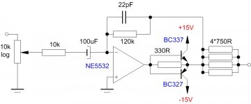
* Switchable output impendance between 32 ohm and 200 ohm.
Source: MP3 player
vital statistics;
Output max 1V into 32ohm (30mw per channel)
This has been bugging me in the back of my head...
And I finaly put the soldering iron down to look up some specific info:
"resistor at the input. Now 20k sound low for a tube circuit, but is wildly high for an MP3 player that was designed to drive a 32-ohm load. In other words, the MP3 player’s internal headphone amplifier will be so unloaded by 20K, that its output stage might even remain in class-A operation. "
This is obviously not a good way to use your Ipod with non replaceable battery.
* So a requirement would be better input impendance matching to the ipod expecting to see 32 ohms on the output.
* PSU: Single 9v for easy portability/small case
(not sure if last request is possible in reality, but here goes)
* Switchable output impendance between 32 ohm and 200 ohm.
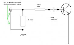
I use to install a load for the Ipod...a low impedance load
Normally i install a 33 ohms resistor in the input, this way Ipod will be happy and will develop its power over the resistor....and them i use to transfer the audio into the amplifier input using series resistors to avoid saturation.
Using this matching trick...to fool the Ipod and the amplifier...they go running happy.
regards,
Carlos
I believe there is an optimal ratio... just to tired from soldering till 4 in the morning, 3 nights in a row, to look it up right now...nevermind actualy understand what I read.
Think its time for a afternoon nap... oh well 4 minutes to go to 12.
Think its time for a afternoon nap... oh well 4 minutes to go to 12.
Thank you Sparkle, as you are beeing kind supplying the thread with schematics
This is very good to me, as i do not need to keep a constant control not to let the thread die so soon.
Go ahead please, i am really enjoying what you are making here
..........................
Nordic
It is just a resistor in the input, with low value that will be seen, by the Ipod, as a nice impedance to it...let's say that the Ipod will work in a confortable way.
The resistor in series will reduce the sensitivity and will also separate a little the Ipod output impedance that could be annoying to the transistor circuit..... having mismatch....this way, both will work better and the mismatch consequences will be reduced.
Just a practical trick, a little bit obvious i know, but use to work fine.
Yes, base biasing resistors where supressed as we need just the indication that exist a transistor circuit at the rigth....not needed details...the left input is the subject of our conversation...also other transistor connections where supressed to make it simple.
regards,
Carlos
Attachments
DC OFFSET ON HEADPHONE?
It can DESTROY your headphones. But... For a man who uses MP3 to loud music, anything can be the MOSTest amplifier on the world.
=]
Don't Worry... Be happy!
It can DESTROY your headphones. But... For a man who uses MP3 to loud music, anything can be the MOSTest amplifier on the world.
=]
Don't Worry... Be happy!
A long time i do not see you Mod Evil
Good to have you here.
In ve jah eh uma ler da!
Remenber that song...brazilian people's song.
hehe
Carlos
Good to have you here.
In ve jah eh uma ler da!
Remenber that song...brazilian people's song.
hehe
Carlos
Destroyer.
If you put DC OFFSET ( many volts in this circuit ), you will damage the voice coil of your headphone it will kill!
My old Philips SBCHP800 killed your voice coil with 0.8v.
I isn't a good idea, put DC OFF ON HEADPHONES.
If you put DC OFFSET ( many volts in this circuit ), you will damage the voice coil of your headphone it will kill!
My old Philips SBCHP800 killed your voice coil with 0.8v.
I isn't a good idea, put DC OFF ON HEADPHONES.
You are rigth..thank you by this information
I hope everything fine in your place.
Here is too much hot those days.
regards,
Carlos
I hope everything fine in your place.
Here is too much hot those days.
regards,
Carlos
- Status
- Not open for further replies.
- Home
- Amplifiers
- Headphone Systems
- New best wide world headphone amplifier