Hi!
I've just joined this forum and read through countless posts made here, trying to learn how to eventually build my own solid state guitar amp. I found an interesting post from a thread from 2007, so I cant really post this there... haha
But I will quote this specific post I am talking about -
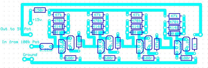
This is the circuit "Minion" is speaking about
Now I play in a hardcore metal/punk band so I thought this could be the perfect first build that I could actually put to use and if I like it I can go on to build a preamp and combine this schematic into it for a gain channel?
I would just appreciate it if someone could help me out a bit and help me read this diagram... Like set me on the right track toward my final goal and stuff 🙂 I'm struggling to work it all out, I'm going to try and draw up a schematic once I understand it better but any help would be gratefully appreciated 🙂
oh btw I'm planning on becoming an electrician of some sort so pretty much anything I build is beneficial I think, is anyone here an electrician for their career?
I've just joined this forum and read through countless posts made here, trying to learn how to eventually build my own solid state guitar amp. I found an interesting post from a thread from 2007, so I cant really post this there... haha
But I will quote this specific post I am talking about -
I am useing this curcuit in my Guitar amp for Distortion and it is honestly one of the Best distortion sounds I have ever heard.....
The design calls for 2n3904 Transistors but I found I get a MUCH better sound useing 2N2222 Transistors....
If you want to use it as a Pedal you could easilly add a Bypas switch so you can Turn it on a off by stepping on the Bypass switch and best of all it will only cost about $4 in Parts at most....
I play Heavy death metal and hardcore Punk type music and this is perfectly suited for this type of Music.....
Cheers
PS: the orentation of the Transistors is reversed in the diagram....
This is the circuit "Minion" is speaking about
Now I play in a hardcore metal/punk band so I thought this could be the perfect first build that I could actually put to use and if I like it I can go on to build a preamp and combine this schematic into it for a gain channel?
I would just appreciate it if someone could help me out a bit and help me read this diagram... Like set me on the right track toward my final goal and stuff 🙂 I'm struggling to work it all out, I'm going to try and draw up a schematic once I understand it better but any help would be gratefully appreciated 🙂
oh btw I'm planning on becoming an electrician of some sort so pretty much anything I build is beneficial I think, is anyone here an electrician for their career?
I just spent some time finding a program and drew up this schematic, is it the same as the one I posted previously? and are the components accurate? I'm not sure if I even drew it right...

I'm struggling to understand how this works, Its a distortion unit but the potentiometers are only at the input and output? so how does the distortion level change? anyways again any help is very much appreciated 🙂
I'm struggling to understand how this works, Its a distortion unit but the potentiometers are only at the input and output? so how does the distortion level change? anyways again any help is very much appreciated 🙂
I expect the pot on the input would change distortion levels, and the one on the output will simply be a volume thingy. I'm not much use at interpretting circuits, so I can't say much else...
Welcome to the forums, anyway.
Chris
Welcome to the forums, anyway.
Chris
Schematic looks OK except for the pots, which are arranged incorrectly...
That's what they should look like. Lower case k is correct but it should be capital R for the resistors.
w
An externally hosted image should be here but it was not working when we last tested it.
That's what they should look like. Lower case k is correct but it should be capital R for the resistors.
w
I was a factory electrician/maintenance man for a while before I quit. Doing nothing/playing music, fixing things for hobbies now. Electrician pays better than electronic technician because you can kill yourself so easily. Also there is slime in the pump pits. Wow, what a twenty first century thing, upper case R for resistors! I'm still trying to find out what "m" means on capacitors, changes depending on decade, continent, maybe what school you attended in what language. Pretty good first job on reading artwork. Look at music-electronics-forum.com if you are interested in guitar amps only, they don't have much patience there for hi-fi equipment, organs, keyboards or other girly things. I was banned. See my signature for my effeminate interests- all except I am a guy and am totally AC. Oh, I forget-that is "bloke" in Austrailian. What is the adjective form of "sheila"? Unless any women get upset, I prefer the company of women, as long as they have interesting hobbies.
Last edited:
hahaha your post made me laugh so much, then I see the end "edit, reason: speak australian. hahahaha...
You did a pretty good job of translating that layout into a schematic. The device uses one of the oldest tricks in the book of guitar distortion devices. That is to use back to back dioded to clip or square off the signal. In this case the designer has elected to put the signal throught that process 4 times. More is better ? right.🙂
Hi,
Something to try (I did this on my old (31 years) SS combo) - add an output transformer. I used a 30VA 12-0-12 torodial. Put the amp across one winding, the speaker on the other. Took the harsh edge off the speaker, gave a more valve-y sound. Might not be what you're after for heavy metal, but sounds nice for other stuff...
Something to try (I did this on my old (31 years) SS combo) - add an output transformer. I used a 30VA 12-0-12 torodial. Put the amp across one winding, the speaker on the other. Took the harsh edge off the speaker, gave a more valve-y sound. Might not be what you're after for heavy metal, but sounds nice for other stuff...
Yeah I'm still trying to work out how everything works, so this is diode clipping, that makes sense 🙂
Thats an interesting idea Chris, I might try it sometime 🙂
Thats an interesting idea Chris, I might try it sometime 🙂
Hi,
Its not a complicated circuit and its repeated 4 times.
Each stage has x10 voltage gain (20dB gain).
TBH for the first two stages the diodes seem irrelevant as there will not
be enough voltage to turn them on. Related to that doubling up the diodes
(in series) on the last stage may help, or using silicon diodes for the last stage
and germanium diodes for the third stage, its an easily tweakable circuit.
😎 /Sreten.
GL66:
You may want to look at one of the DIY pedal forums. They have a lot of simpler schematics for clipping and overdrive. One claims like "infinite sustain!". Hehe. Anyway, the forum really explains the whole homemade idea pretty well.
PS: those pots are NOT drawn wrong. If you look, they are functioning as variable resistors: hook the wiper (middle terminal) to the input or output leg. The pot can then be turned from zero ohms to the full value of the pot - 5K or 100K ohms. This will behave differently than running them to ground as a voltage divider.
I have an associate's degree in electronics for cred, I'm certainly not an engineer though.
PS: those pots are NOT drawn wrong.
Yes they are, they wouldn't work like that - particularly the output one which would do nothing when turned from end to end.
Hi GL66
The little distortion unit I use is only one of those transistor circuits. I'm not into real heavy metal type music but it sounds great. 9V battery lasts a year and longer. I can't remember the component values but the layout is the same. If you're just starting out, you might want to build one section and get it working like you want, and then move on. Loads of pedal schematics on the net. I'm no expert - just my thoughts.
The little distortion unit I use is only one of those transistor circuits. I'm not into real heavy metal type music but it sounds great. 9V battery lasts a year and longer. I can't remember the component values but the layout is the same. If you're just starting out, you might want to build one section and get it working like you want, and then move on. Loads of pedal schematics on the net. I'm no expert - just my thoughts.
- Status
- Not open for further replies.
- Home
- Live Sound
- Instruments and Amps
- New and need some help :)