Thanks for the defense davada,
Lineup,
I am not contesting that I need a zobel or not, just asking why you were so adamant about your suggestion. Must have had some experience to make you so... Thus I just wanted to know what it was, Not saying that you are wrong in its necessity.
Continued testing:
Well I couldn't add just a resistor across the Bases without constant oscillation, but I did scrounge a package of paper/oil caps that are 0.22uf, so i put one of those across it by itself and it does seem to increase the point at which oscillation starts. I.E. its seems more linear now.
For instance, it almost looks stable under an 8ohm load now with almost all input, awesome! 😀 I tried it with a few waveforms, a nasty square and sawtooth, as well as a clean triangle and sine. They all followed very cleanly at 8ohm up to the computer output voltage, more squirmy like before at 4ohm.
I can see with the multimeter that the voltage is not very constant across that cap when playing music, so it apparently needs to be a bit bigger. I assume the idea is to get the bases to be at a mostly constant voltage offset.
a question my friend zobel...
Why use a 10ohm resistor on the zobel, why not more attenuation? Like a 2ohm 110nF filter, I would figure if you were going to deaden the higher frequencies, why not really go after them?
I.e. Why not test an amp without the zobel, be sure it has no real stability issues, then add on the high frequency zobel damper and get rid of all the crap above 50 khz, intermodulation etc... An input filter should also do the same on the input side so accidental/intentional signals don't overheat the network.
I dunno what to do about the inductor, I know damping is good for low frequency reproduction but I don't know the real implications of it. I'll probably plan to try it out and see what happens.
also if there's anything that anyone would like to investiage I'm more than happy to be a guinea pig.
Last edited:
Hi Buzz1167,
Here is a link to an article I think you would benefit from reading.
Elliott Sound Products - Audio Power Amplifier Design Guidelines
Here is a link to an article I think you would benefit from reading.
Elliott Sound Products - Audio Power Amplifier Design Guidelines
Very Epic! Thank you a lot for that gem of an article! I don't know if I can sleep until I finish it.
Awesome! Thanks to everyone who helped me get this far!
I installed the Insulating pads, which didn't do much, but I think it is safer this way so I'll keep using them.
I read that article above and ended up putting in an RF filter for the input, which also didn't fix the problem.
The Zobel network certainly fixed (or masked) the issue though. I used a 5W, 5Ohm with a .1uF polyprop cap. I have been worried about the power dissipation because the oscillations could get quite unwieldy sometimes... But apparently its not very bad. I've cranked it with a 4ohm load on +-30V and got to just below clipping for about 30minutes or so and the zobel resistor isn't warm but the heatsinks are getting there 🙂
I also notice that if I attach my oscope lead to the input and I'm using the x1 option, that the lead attachment also apparently makes the input and output oscillate. Switching to the x10 removes the oscillation but makes the signal noisier/smaller. Also, attaching the lead before the RF filter does the trick too, and I don't need the x10 option anymore.
Does anyone know a way to get rid of this noise that the oscope is adding without limiting it's frequency response or gain?
Last edited:
You're seeing the noise floor of the vertical amplifier in the scope when using the x10 on the probe. You have to increase the scopes sensitivity when using x10 and that put closer to the noise floor. A better scope is about the only way to get the noise down.
hi buzz1167,
If you built your amp in accordance to the schematic in post#3, check the orientation of the caps on the rails. I believe the schematic is wrong.
regards
If you built your amp in accordance to the schematic in post#3, check the orientation of the caps on the rails. I believe the schematic is wrong.
regards
ok so the noise won't go away with the scope I have, I can deal with that. Do you know of any methods to use an oscilloscope to measure distortion? Any way to get an idea of the THD? On my scope, using the setting that fits the signal across a full screen, I am hard pressed to decifer it from a pure sinewave, I.e. No visible distortion to me.
when I invert the signal and add the output the gain is not an exact ratio on my oscope so I have to vary one of them to minimize the difference and I generally get a much smaller sinewave. If I zoom in a few times, around 5 or 10 I can see what seems to be a sharper signal (not sinewave) but I can't figure a way to change it, playing with the bias doesn't seem to make it change.
Greg, the schematic is in error, I was lazy and just wanted to cut and paste, I figured yall could work it out.
Last edited:
No low distortion is not possible on a scope because the noise floor is greater than the distortion. The typical 20 MHz scope only goes down to 5 mV/div. The reason is because of the bandwidth of the vertical amplifier. Noise power is proportional to band width. So the only way to reduce the noise power is to lower the bandwidth of the vertical amplifier. Secondly, the scope would have to have a band pass filter that could selectively capture the harmonic(s) of interest.
Some specialized scopes have a feature to lower the bandwidth so noise measurements are possible down into the micro and in some cases even the nanovolts. Filtering the input to the vertical amp will help some but only for the external noise not the internal noise. This is the nature of general purpose scopes, wide bandwidth.
You can view the residual output from a distortion analyzer on a scope.
Last edited:
Ok so I hope to get some input based on these photos I have of the output, I don't know if its just crap from the oscilloscope or its actually from the amplifier.
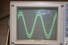
I have the output on x10 and the input on x1. Simple signal, just a sine wave. I think its a 1khz. I forgot already 🙁
I have a picture of the input and output signals matched as closely as I can with the variable voltage adjuster.
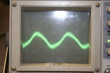
Then I go down to 10mv, subtracting the two signals.
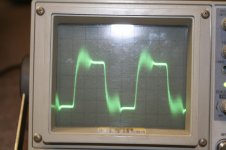
5mv
2mv
1mv
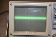
Then a picture of 1mv with the input unplugged from the computer (background noise or some cheap idea of it) I probably shouldn't have left the subtraction function on, but that's what I did...
The problem I have is that when I decrease the voltage increment, the picture stays about the same size, wtf is up with that? I dunno what to think.
I have the output on x10 and the input on x1. Simple signal, just a sine wave. I think its a 1khz. I forgot already 🙁
I have a picture of the input and output signals matched as closely as I can with the variable voltage adjuster.
Then I go down to 10mv, subtracting the two signals.
5mv
2mv
1mv
Then a picture of 1mv with the input unplugged from the computer (background noise or some cheap idea of it) I probably shouldn't have left the subtraction function on, but that's what I did...
The problem I have is that when I decrease the voltage increment, the picture stays about the same size, wtf is up with that? I dunno what to think.
Attachments


- Status
- Not open for further replies.
- Home
- Amplifiers
- Solid State
- New amp testing, Noob needs input.