Built a amp using two kit-lion monoblock amp kits. This was my first audio build and I am happy it came out very well. Joined this forum to seek some help on tweaking it a little bit. It seems a little harsh - but sounds very good. Each kit uses 2 12A6 (RCA tubes) and a 6EB8 (I think soviet) and I don't know enough about tube choices for audio.
I have a physics degree and understand enough electronics, and done a little reading before I chose and built this amp on a relatively limited budget.
Any suggestions for improvements (what info do you need), it was so much fun to build and will be building a preamp soon (any suggestions)
I am playing a Music Hall MMF7 through s SS preamp that was given to me and 8 ohm home built speakers from a friend (that sound great through CD or the TT).
Should I play with the resistor size on the speaker outs? This was one thing I wasn't sure if I should use 10k, 100k, or 1M resistor the kit had all three.
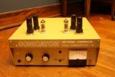
This was an all point to point build, housed in a great box from an old cell disrupter called the "sonicator" pic attached below.
Eric
I have a physics degree and understand enough electronics, and done a little reading before I chose and built this amp on a relatively limited budget.
Any suggestions for improvements (what info do you need), it was so much fun to build and will be building a preamp soon (any suggestions)
I am playing a Music Hall MMF7 through s SS preamp that was given to me and 8 ohm home built speakers from a friend (that sound great through CD or the TT).
Should I play with the resistor size on the speaker outs? This was one thing I wasn't sure if I should use 10k, 100k, or 1M resistor the kit had all three.
This was an all point to point build, housed in a great box from an old cell disrupter called the "sonicator" pic attached below.
Eric
Attachments
I'm not able to find it doing a google search.
If you can post a link to the kit and a schematic it would be most helpful.
If you can post a link to the kit and a schematic it would be most helpful.
here...
THe meter isn't hooked up, was trying to figure out what to use it for, as it was already in the case but for bias, that is a good idea hmmmm...
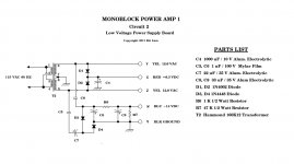
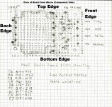
Here are the schematics. I am afraid I enjoyed the build too much and am in some trouble. The wife "loved" me hunched over an soldering iron in the basement... : )
THe meter isn't hooked up, was trying to figure out what to use it for, as it was already in the case but for bias, that is a good idea hmmmm...
Here are the schematics. I am afraid I enjoyed the build too much and am in some trouble. The wife "loved" me hunched over an soldering iron in the basement... : )
Attachments
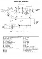
There's not much to that circuit. It's very old fashioned; no global feedback.
What kind of output transformer does it use?
You may be able to balance the sound out by just adding a preamp with tone controls or a graphic equaliser. Conversely, it might sound a lot better driving different speakers, especially higher Q speakers like they used to have back in the day.
More "modern" tube amps work a lot better with modern speakers than a quaint amplifier like that. That is because they are relatively wide bandwith, global feedback designs with loop gain as high as is practical. This makes for a fairly linear, high damping factor amplifier which is what the whole modern "hi-fi" market is geared towards. What you have there is more of a "tweaker" amplifier that might be "quirky" with some speaker systems.
If the output transformer is really terrible, there is probably something to be gained from swapping that out. Pics?
will do
Thanks for the feesback. It is basic but my first build. Will put out more info tonight. Looking to build something more modern this summer. I was happy it came out and actually sounds good. Was going to borrow an eq to play around witj but was hoping to avoid adding to the chain.
How much will the sound change as i only have about 15 hours played on it.
Interesting circuit.
The output tubes are designed for operation in an automobile as a SE output tube. 250V @30ma recommended operating point.
It looks like over 300V on B+ based on a rough calculation.
-14Vgk looks like about 23mA on the plate curve, so dissipation is 6.9W
Pd max of the tubes is 7.5W
Depending on actual B+ he could be at max dissipation.
The Hammond transformer is a tad light as it is specified for 8W out, but the amp probably is producing about that.
The design has pins 3&6 to an 8R speaker, so p-p Z is about 6.8K. That is way low for the tubes in question as they are specified for 7.5K SE. The transformer taps should be more like 4&6.
It think there is a bit of a miss match in the output impedance that is increasing distortion.
Last edited:
Doesnt the cathode follow the grid on the PI? So isnt the potentiometer placed there not really doing much? I cannot see how it'll be a voltage divider when there's no current passing thru...
Still, great to have another tube geek join us. It just gets better...
Still, great to have another tube geek join us. It just gets better...
Yes, the volume pot placement looks a bit strange. I suspect it will give an unusual 'law': neither log nor lin.
What value do you have for R25? if it is 10K, you might change it to 100K to keep from loading the source as heavily.
C14 makes me wonder if there is a resonance issue, possibly with the output transformer.
C14 makes me wonder if there is a resonance issue, possibly with the output transformer.
C14 (and R24) will roll off the treble. This amp looks a bit like the kit amps which were advertised in 1960's magazines: a strange hybrid of (low power) PA, guitar and audio but lacking the features which would suit an amp to one of those applications.
Which is precisely what is done in some amps to band-aid a transformer resonance problems.
Moyle in "Amplifier Response Stability & all that" (1958 Radio discusses it to control transformer resonance. Although he used a series RC step attenuator to do it, a single cap can also be used.
http://www.tubebooks.org/file_downloads/moyle_amp.pdf
Although Moyle was referring to feedback amps and this one has none, so as you say it is probably just HF roll off.
Last edited:
thanks
I appreciate all the input as this is relativwly new to me and it is such a simple amp. It really sounds nice for what it is. Going to swap in the 100k and see.
Have read thus forum a lot and hope to be a part of it more now since my feet are wet.
Anyone want to point me to a good preamp design for my turntable MMF7. I want to do that before another amp build.
- Status
- Not open for further replies.
- Home
- Amplifiers
- Tubes / Valves
- new amp build