mmm. I built mine and use it single ended - but I never tied in- to gnd. Must do that now - but will it make any sonic difference?
Fran
Fran
ok. If the offset is ok that way I will leave it that way. Do not change a running system 🙂
What about the temperature? I ordered me some fans to cool the whole enclosure...
thanks a lot!
Fans are a noisy. How hot does the heatsink get? A temperature of 50°C is no problem at all. A rule of thumb: if you can touch the heatsink for 2 seconds or longer you're good to go. Make sure the enclosure has ventilation openings on both top and bottom.
OK...more progress...
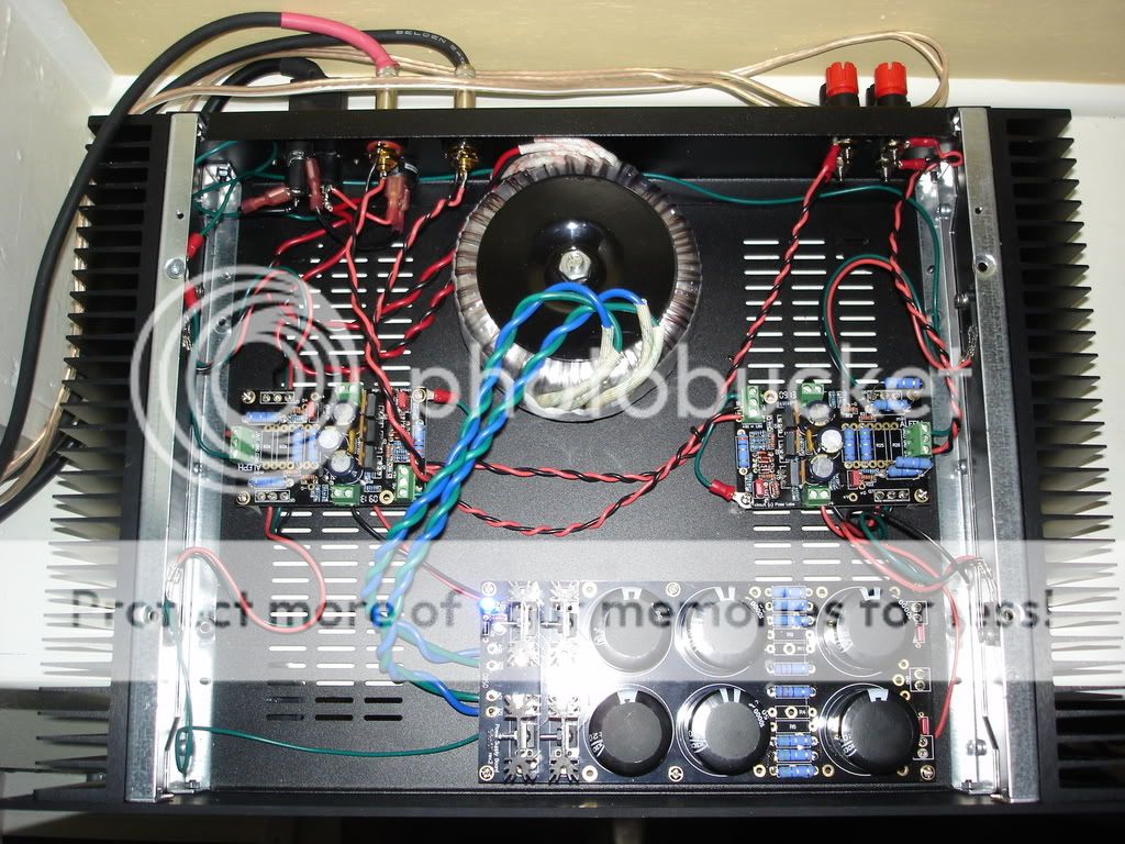
I have the chassis 99% done...I think I am just down to shortening the leads for the power FETs...
I spent this morning trimming the rest of the wiring and twisting all A/C runs...
The amp is very silent on my Universal Chip Preamp...Haven't tried it with the Aikido yet...and it sounds very nice...
The heatsinks were quite cool so I mounted another pair of 0.47 ohm resistors on the right channel. So it is now running about 2A bias and the heatsink is hot but I can hold my hand on it "indefinitely"...V+/V- is running now at a loaded 15V.
I just noticed your post, if you change the source resistance you also need to change the sense resistance accordingly. As you have it the AC current gain is greatly changed from the design. Add two more .47 ohm resistors to the sense resistor position.
I just noticed your post, if you change the source resistance you also need to change the sense resistance accordingly. As you have it the AC current gain is greatly changed from the design. Add two more .47 ohm resistors to the sense resistor position.
Thankyou for the clear pics showing your wiring. I've been searching for such pics. Very nice job by the way.
Russellc
I have got holes in the top and bottom but the temperature rises to 60°C. I ordered fans that make 23db at 12V and I will try to reduce the current according to the temperatur. I have my camera in my office, but I will post some pics during the next week. Maybe you have some suggestions how to make it better.Fans are a noisy. How hot does the heatsink get? A temperature of 50°C is no problem at all. A rule of thumb: if you can touch the heatsink for 2 seconds or longer you're good to go. Make sure the enclosure has ventilation openings on both top and bottom.
I think the heatsink inside the enclosure is not the best idea, but i wanted to have the amp in a 19" rack system/enclosure!
Greetings.
boris
PS: Great! I can post without an admin now! I am free! 🙂
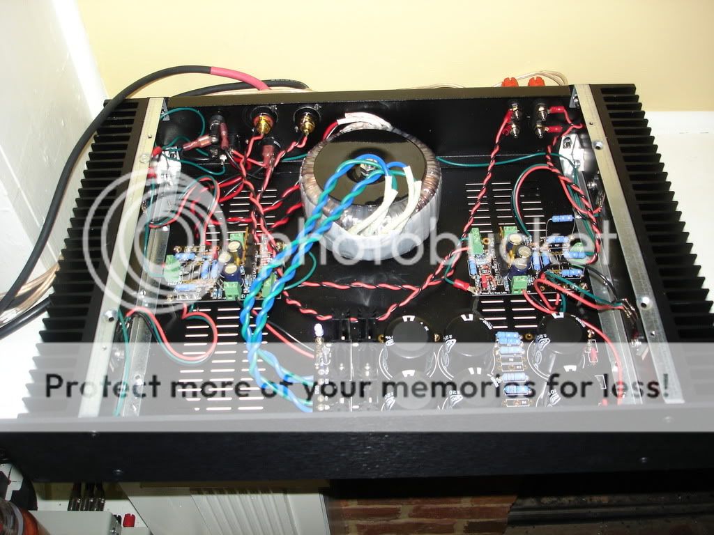
Those pics are cjkpkg's amp, it does look very nice.
If I'm not mistaken though, it looks like he has signal ground tied directly to the chassis. Not really a great idea, maybe he will respond. Also, the trafo is much too close to the input wiring.
If I'm not mistaken though, it looks like he has signal ground tied directly to the chassis. Not really a great idea, maybe he will respond. Also, the trafo is much too close to the input wiring.
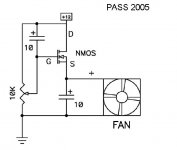
If you search around, there is a very simple circuit to control fan speed by nelson. Gives a shot of current to start the fan but then cuts back to run the fan at low speed and very quietly.
Fran
Fran
Boris,
Do you have any inrush limiting on the amp? A CL-30 in series with the mains will help. With CL30 and a 1KVA transformer followed by 90Kuf I found that I needed a 6A slow blow to keep from occasionally blowing the line fuse on start I have 120V mains, so your 2A slow blow ought to be in the ballpark.
If you can keep your hands on 60C sinks you are a better man than me. Each output FET will have a thermal resistance of 0.86 C/W junction to case and maybe .7 to 1 case to sink depending on your isolator choice (what did you use?). Therefore, the junctions will be 20W x (1.5 to 1.9) hotter than the sinks. That makes the junction temperature around 90 -105C. That is well within their ratings, but if anyone can come into physical contact with the sinks, it's probably better to have them a bit cooler.
Hi guys - thanks for the kind words...
For the Mini-A I actually have changed a couple things...
-I am using 0.39 ohm source resistors now...I forget the amount of bias now but I think it is about 1A per FET.
-For input and output wiring I am using a belden shielded cable - seems to have quieted things down nicely.
-For the PSU I acually switched to Peter Daniel's universal PSU using some Vishay GBC rectifiers and 2X39,000 uF per rail.
This combo has made this quite a nice little amp. I realize that the trafo is a little too close but things are quiet now and I think I am pretty well done fussing with it for now.
Once I get my 2 ways done I would like to play around with bi-amping using this little guy on the tweeters maybe.
HI Bob,
Thanks for the reply. My English and especially my technical English is not that good. Can you please explain what you mean with CL-30. If we are talking about the power supply section i can tell you that i have a CRC there. The C1 is 22kµF followed by a 1 Ohm 5W resistor and again 22kµF capacitor.
I did not put my hands on the heatsink. I measured it with a PT100 and multimeter / circuit analyzer. Put the front and back of the enclosure were not mounted for testing the aleph. So I think with closed enclosure the heat will rise even higher. I have mounted the FET with a mica disk (if leo.org has translated the German word: Glimmerfolie right).
For protection of children or drunken guys in my living room all heat sinks are inside the enclosure.
I want to regulate the speed of the fan with a potentiometer as a changeable resitor. The Fan works for 12V and I hope it will be able to turn at 6V or less as well.
I will try to post a picture now...
edit:
http://www.analog-forum.de/wbboard/index.php?page=RGalleryImageWrapper&itemID=37736&type=page
sorry, I only have the link to the german forum. I don't have the original picture available here right now...
Bye.
boris
Last edited:
CL-30 and CL-60 are different types of NTC (negative temperature coefficient - they drop resistance as they get hotter) resistors, that can be used as inrush current limiting.
This datasheet describes their specs - www.thermometrics.com/assets/images/cl.pdf
This datasheet describes their specs - www.thermometrics.com/assets/images/cl.pdf
Hi Atilla,
Thank you for the explanation. That might be a solution.
edit: Do I change the resistor of the CRC for this thermistor?
Thank you for the explanation. That might be a solution.
edit: Do I change the resistor of the CRC for this thermistor?
Last edited:
No, it goes in the line connecting the mains to the power transformer primary - TH1 in the schematic on the first page here: http://www.passdiy.com/pdf/a75p2.pdf
CL60 is probably a better choice for your application. I used CL30 for a higher current application.
CL60 is probably a better choice for your application. I used CL30 for a higher current application.
I have just looked at a German suppplier's Homepage and found some Thermistors. I do not know what kind to choose. I have the normal 18V Version of the Aleph Mini and one transformer for two mono PCBs. The Transformer has a maximum power of 500W and as far as I could find out the current for each mono block is 1 A. I am running the amp in Germany with 230V.
Any suggestions for the current, voltage or power of the thermistor?
Thanks a lot.
Boris
Any suggestions for the current, voltage or power of the thermistor?
Thanks a lot.
Boris
Note - NTC = Negative Temperature Coefficient, meaning that the warmer they get the lower the resistance. You don't want the Positive TempCo types. Take a look at the data sheet Atilla linked to - You want something like the CL-60, perhaps two in series.
aleph 5 PSU with Aleph mini PCB
I built two mono Aleph's 5 with amazing BrianGT's pcb too.
Work perfect. Brian in his PSU partslist (for this configuration) recommended 6x10mF caps for each channel only. Original Aleph5 used 4x25mF, Kristjan Kljucaric (kk-pcb-dot-com) prescribed 8x22mF... etc...
So, is this 6x10mF adequate, or should I add some bigger cap?
Sorry if this is asked before.
Cheers!
Mini Aleph 30 with virtual ground, finally Singing!!
Finally, I manage to finish(??- not in the case yet) mini aleph 30 with virtual ground using dead Crown ce1000 transformer. I copied Quad virtual ground circuit to equalize + and - rail. Without virtual ground mod, amp fails to run in few min to seconds by having + rail collapsed to near zero. I have been listening my new aleph mini for 1 day and half. I really like its sound and heat. It is making my man cave warm and cozy. I'd like to thank Mr. NP for his kindness.
Finally, I manage to finish(??- not in the case yet) mini aleph 30 with virtual ground using dead Crown ce1000 transformer. I copied Quad virtual ground circuit to equalize + and - rail. Without virtual ground mod, amp fails to run in few min to seconds by having + rail collapsed to near zero. I have been listening my new aleph mini for 1 day and half. I really like its sound and heat. It is making my man cave warm and cozy. I'd like to thank Mr. NP for his kindness.
Sorry guys, I just need to check something.
Using the amp single ended on the brianGT boards. Ground the neg input and use GND and + right?
Fran
Using the amp single ended on the brianGT boards. Ground the neg input and use GND and + right?
Fran
- Status
- Not open for further replies.
- Home
- Amplifiers
- Pass Labs
- New Aleph Mini PCB GB