Soon
Just a little more to finish then I will post pictures of the innards. Waiting for some binding posts for the speaker connections, and have to solder up final wiring to the on / off switch etc. Maybe in a few days.
Care to share the inside? Thanks.
Just a little more to finish then I will post pictures of the innards. Waiting for some binding posts for the speaker connections, and have to solder up final wiring to the on / off switch etc. Maybe in a few days.
Pass DIY Addict
Joined 2000
Paid Member
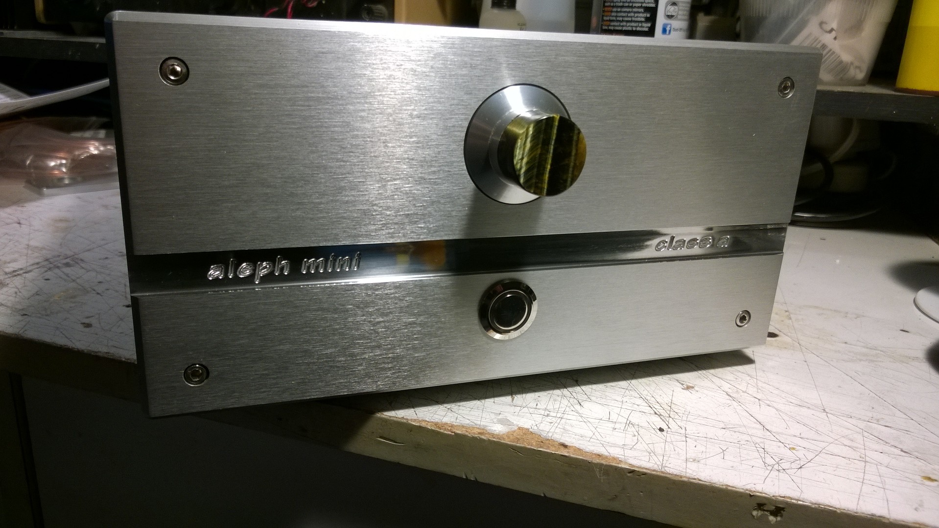
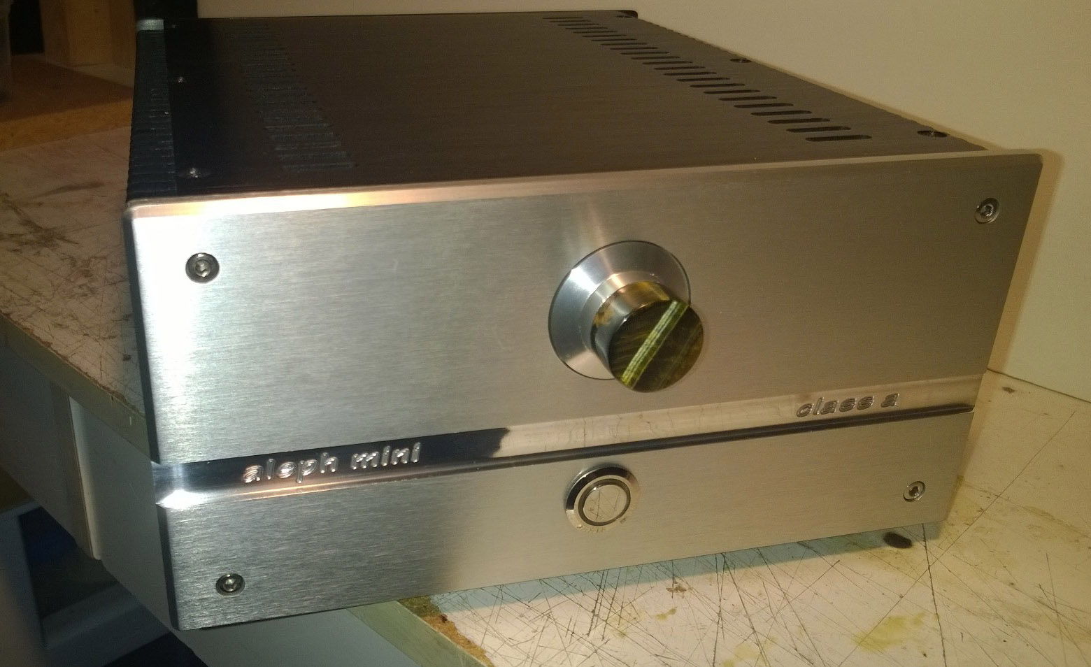
All finished
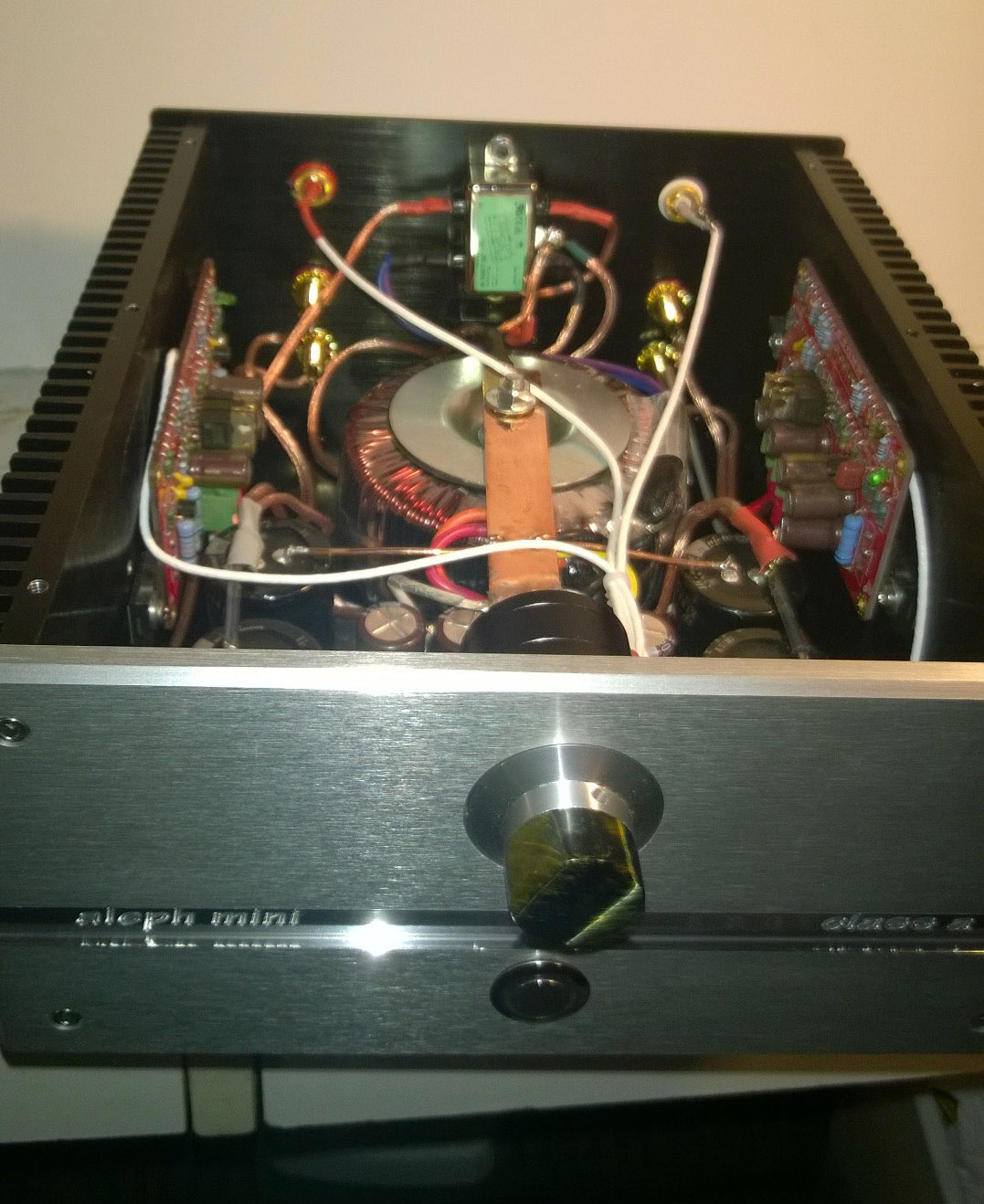
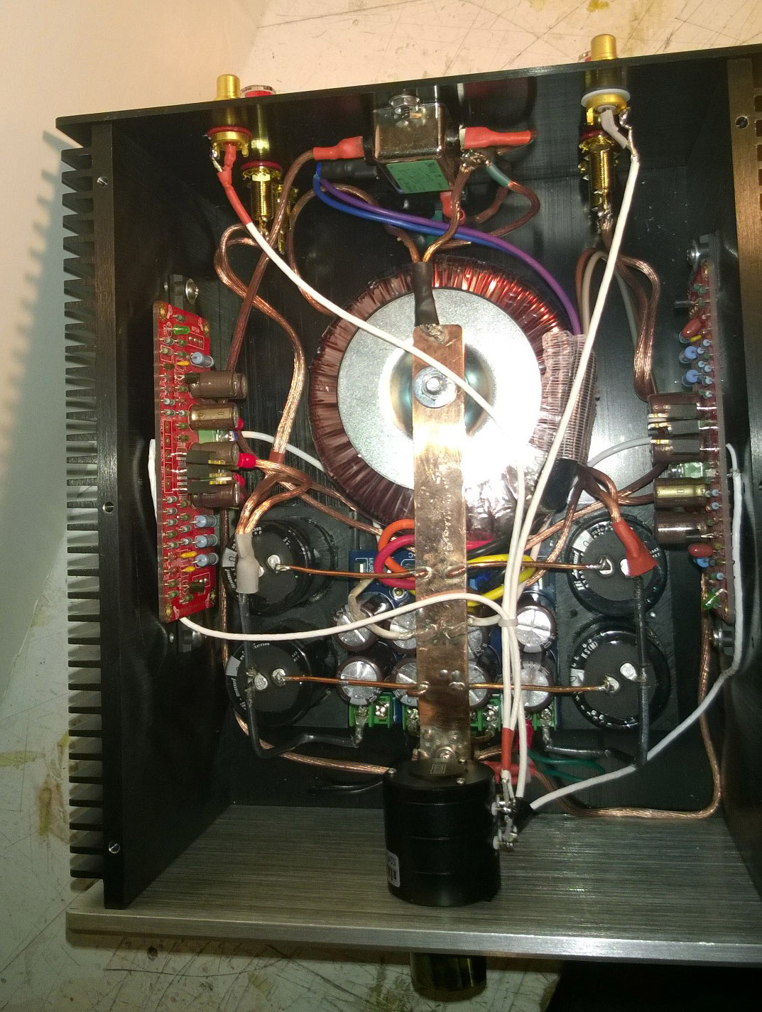
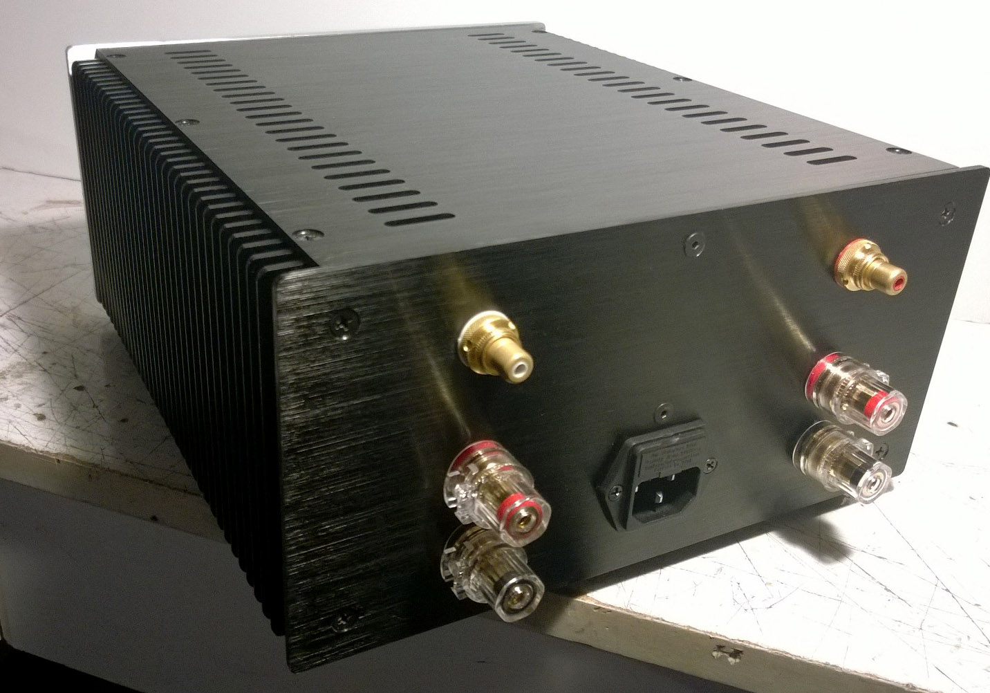
I finished. Nothing special inside, except maybe the copper grounding bus.
250 VA transformer there, for a ~10 watt/channel amp....
Supply voltage is ± 15.75 Volts dc
Supply capacitance is 62,800 per rail - all Nichicon "audio grade" caps.
Input wiring is silver-plated / teflon coax
22 step Eizz 50k stereo attenuator used
Gold plated copper RCA input jacks (not brass)
Large binding posts for output
OFC 14 ga wiring used for output wiring from amp boards to output binding posts
Series resistor limits brightness of white LED-lit ring on power switch, 'ON" is indicated by a somewhat subtle glow, as opposed to an indicator that is bright enough to read by....
Last edited:
Shorted turn ?...copper grounding bus...
Attachments
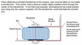
That's intersring, I had not thought of that. I can replace the bolt though the transformer with a nonferrous bolt, or even a reinforced nylon bolt.
I wonder what kind of voltage is induced here. FYI the copper bar is not bolted to the chassis at any point. The rear of the coper bar is bolted to the transformer retaining bolt, and the front of the copper bar is attached to a delrin post. But, a copper wire does connect the bar to the account line safety ground, on the back panel.
I'll put a nonferrous bolt in there, that should eliminate any interaction with the transformer.
What kind of problems could this shorted turn cause? There's no hum or noise in the amps output.... I suppose the shorted turn could heat up if there was a significant current flowing....
Using a non-ferrous bolt will not fix the problem. That wire in you tube video is not ferrous. A non-conductive bolt will help, but better yet, do not connect the bus to the center bolt. Maybe put a spacer there to make sure they do not touch.
Put the transformer on a non-metallic base raised off the chassis about 1/2" to 3/4" and use nylon bolt, washer and nut. Will sound better. One of the easiest and least inexpensive mods there ever was.
I have used layered Plexi-glass.
I have used layered Plexi-glass.
No current
I don't think so.
I opened an air gap between the copper bar and the chassis, and I measured NO VOLTAGE there, to the limits of my ability to measure - so, less than 0.00 mV of AC (or DC for that matter) and also looked at current that might be flowing through this "shorted turn" and found less than 0.00 uA of AC. This is the lowest limit of my ability to measure. So, no, the assumed "shorted turn" created by my copper bar is not real, it is not a problem.
I listened to the amplifier and then replaced the steel bolt through the transformer with a nylon one, and listened again. There is no difference in sound.
In best case it will just melt without burning your house.
I don't think so.
I opened an air gap between the copper bar and the chassis, and I measured NO VOLTAGE there, to the limits of my ability to measure - so, less than 0.00 mV of AC (or DC for that matter) and also looked at current that might be flowing through this "shorted turn" and found less than 0.00 uA of AC. This is the lowest limit of my ability to measure. So, no, the assumed "shorted turn" created by my copper bar is not real, it is not a problem.
I listened to the amplifier and then replaced the steel bolt through the transformer with a nylon one, and listened again. There is no difference in sound.
Last edited:
Not so hot, after all
Here's a thermal imager view of the amplifier. White is the hottest, then red, yellow. Blue and green are the coolest colors.
I ran the amplifier for four hours then removed the cover and took this thermal image.
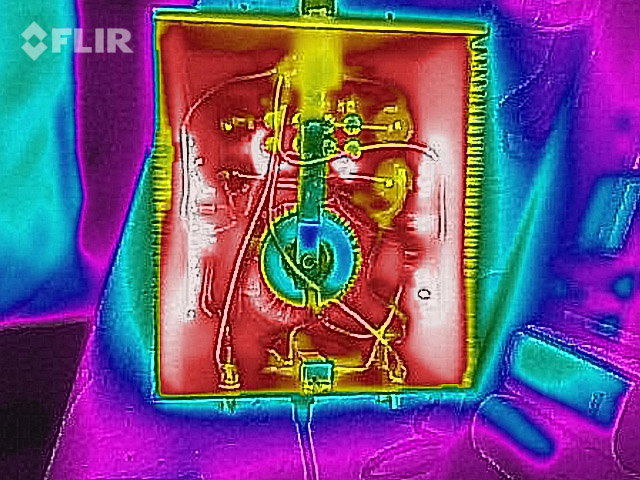
CLEARLY the copper bar - the "shorted turn"- is the COLDEST object inside the amplifier. Now, who was it that said that the "shorted turn" would either melt the amp or burn my house down? I guess this thermal image should put that flawed idea to rest.
Here's a thermal imager view of the amplifier. White is the hottest, then red, yellow. Blue and green are the coolest colors.
I ran the amplifier for four hours then removed the cover and took this thermal image.
CLEARLY the copper bar - the "shorted turn"- is the COLDEST object inside the amplifier. Now, who was it that said that the "shorted turn" would either melt the amp or burn my house down? I guess this thermal image should put that flawed idea to rest.
Last edited:
Is the main PC board for this amp the off the shelf board that's for sale at the DIYAudio.com store?
I got these boards maybe 7 years ago.... can't remember where... stuffed them and then had them around for years.... never did anything with them till now.
Sprags,
hope that information can help you.
10W SE Mosfet pure class A stereo amplifier PCB ! | eBay
only bare pcb - rest is your choice.
BrainGT has also worked out a PCBord. Lykked has it's own project on Aleph Mini (30) clone.
milosz
I must ask: which is the bias point you are running the amp?
hope that information can help you.
10W SE Mosfet pure class A stereo amplifier PCB ! | eBay
only bare pcb - rest is your choice.
BrainGT has also worked out a PCBord. Lykked has it's own project on Aleph Mini (30) clone.
milosz
I must ask: which is the bias point you are running the amp?
As Bangla H suggests, 10W SE Mosfet pure class A stereo amplifier PCB ! | eBay
Those look like the boards I used
I have bought other things from this eBay vendor - Jim's Audio- over the years, such as a regulated B+ supply board for a tube preamp, and some other items, Jim's Audio seems a very good vendor.
Those look like the boards I used
I have bought other things from this eBay vendor - Jim's Audio- over the years, such as a regulated B+ supply board for a tube preamp, and some other items, Jim's Audio seems a very good vendor.
Bias?
milosz
I must ask: which is the bias point you are running the amp?[/QUOTE]
I built the board according to the schematic
So, whatever bias this schematic design incorporates, that is the bias I used. Each board draws 2.15 amperes current from the power supply-
milosz
I must ask: which is the bias point you are running the amp?[/QUOTE]
I built the board according to the schematic
So, whatever bias this schematic design incorporates, that is the bias I used. Each board draws 2.15 amperes current from the power supply-
- Status
- Not open for further replies.
- Home
- Amplifiers
- Pass Labs
- New aleph mini build