Thank you.... the reason I ask, is because I was thinking of mating the SB15CAC with the Seas DXT to have better power response match.
Like this:
Heissmann Acoustics | DXT-MON RLY | Monitor speaker
Like this:
Heissmann Acoustics | DXT-MON RLY | Monitor speaker
Hypex should be looking to you for advice on how to do this 😉. Their manual has been shown in the past to make it too easy with this suggested procedure.The Hypex-recommended filter design approach is to eq the drivers to be flat for at least 1 octave beyond the crossover point. The tweeter did not need any eq within its operating range (pass band), but it had a shallow roll-off below 3k when mounted in my cabinet.
Good project.
Thanks... After reading the manual, I realized that I understood the Hypex filter design process only because I have done multiple passive crossover designs in the past. If I was doing all this for the first time, I might have been spinning my wheels for a long time.
The Hypex product is absolutely first class... the documentation leaves some room for improvement...
There is a Hypex thread in the "Class D" section with about a thousand posts... reading that thread helped a lot, particularly the posts from "YSDR".
The Hypex product is absolutely first class... the documentation leaves some room for improvement...
There is a Hypex thread in the "Class D" section with about a thousand posts... reading that thread helped a lot, particularly the posts from "YSDR".
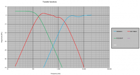
Sorry Jim I lost track of this thread. Thanks for posting all those details of FR curves and the transfer functions. I've posted mine for what it's worth. I'm trying to go for a waveguide on the 26ADC to see if I can push the HD lower for the SB17NBAC with a lower crossover point. I may not need this in practice, so will mock up 2 baffles and do some listening.
In anycase, here's my xfr functions.. all sims so far - for a comparison for what its worth. No LT on the low end (but that will no doubt get an in room adjustment).
Glad to hear it's all working out really well.
PS: there is no attenuation in the breakup with the attached (5Khz +) - I'll do some listening without and some HD sweeps and see if a low Q notch is in order
Attachments
Last edited:
I have become curious about waveguides, but I know virtually nothing about them. I look forward to hearing about your project as you progress...
I have become curious about waveguides, but I know virtually nothing about them. I look forward to hearing about your project as you progress...
I am in the same boat. I want to try simply because they seem popular and an area I don't know much about.
I was going to use it as my "backstop" to a lower crossover point if needed to make the SB17NBAC play cleaner (as far away as breakup as possible) without SB26ADC strain. Good thing is the ADC has twice the xmax of my existing 3 way seas 27tdfc, and that handles 2KHz without problem (although ~ 6th order slope).
I also want to play with beveled edges for diffraction - specifically a stepped baffle edge (22.5 degrees then 45 degrees) which is close to a full radius curve without the complications to construct. I will try 2 baffles - one with waveguide and one without... as well as an IEC type "control" baffle to see if the effects hamper or help the waveguide or faceplate only mounting.
Hello, beautiful project, nicely built!
I also like your wood workshop a lot ;-)
are the measurements been made in the room or outdoors?
have you tuned the lowshelf for the SB34 by ear?
I also like your wood workshop a lot ;-)
are the measurements been made in the room or outdoors?
have you tuned the lowshelf for the SB34 by ear?
The measurements were made in the room.
I did the linkwitz tranformation by hand (although there is an Excel spreadsheet to help with this). I calculated that the 70 liter sealed box with no eq would result in a Q of 0.9, an f3 of 35 Hz, and an f6 of 28 Hz.
I knew I needed a shelf filter which produced 6 dB of gain at ~ 28 Hz, 3 dB of gain at 35 Hz, and 0 gain above 40 Hz. I added a 2nd order shelf filter and adjusted the Q until it produced the response I wanted, which turned out to be a Q=1 and a center frequency of 33 Hz.
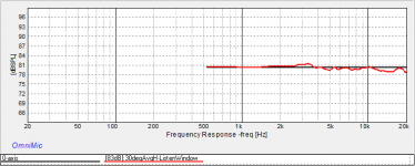
I finally got around to making horizontal off-axis measurements, which digitalthor asked about earlier.
The first curve is the listening window response averaged over +/-30 degree horizontal, normalized to the on-axis curve
The second plot is the horizontal off-axis response at 0, 15, 30, 45, 60, 75, and 90 degrees. I used an improvised "spin-orama" to do this.
I also did some distortion measurements at the upper end of my normal listening volume, approximately 95 dB
Attachments


I'm very interested in those SB ceramic drivers. Measurement looks all great, and I wonder how they would sound (subjectively). Any special strength or coloration you have noticed?
I'm very interested in those SB ceramic drivers. Measurement looks all great, and I wonder how they would sound (subjectively). Any special strength or coloration you have noticed?
Yesterday 03:57 PM
Regarding both the SB17 woofers and the SB26 tweeters: My measured on-axis response curves were almost an exact match to the published on-axis curves from SBA, and there was almost no difference between the left and right drivers.
Subjectively, they have a lot of detail and clarity. Especially in the very soft quiet moments where they maintain details down to very low SPL. This allows them to convey a very realistic studio or hall ambience, where a plucked string slowly fades to black, or a cymbal rings down to nothing. They transition from soft to loud to soft very realistically.
My old speakers https://www.diyaudio.com/forums/multi-way/343405-school-3-build-26-ago.html#post5931616 used polycone mids (Vifa P13MH series) and aluminum dome tweeters (Vifa D25AG35) and these were very easy to listen to, very smooth, but they did not convey nearly as much detail as the SB ceramic drivers do. When I first realized how much detail I was getting out of my new system, I was concerned about listener fatigue… but that has not been an issue. I can listen to music for hours on end. This system is also used with our TV, and we watch a lot of movies from DVD/bluray/streaming… No listener fatigue at all.
Like most hard cone drivers, the SB17CAC have rising response at higher frequencies, and a complicated off-axis response. A passive network will need to be fairly sophisticated to handle this. With DSP active, I was able to handle it without problem.
I use a DATS v3 to measure driver impedance and T/S parameters. I found the SB17CAC35 drivers to have T/S parameters quite different from the published values. This was before break-in. If you search the threads, you will find that others have noticed this as well with some of the other small and mid sized SB woofers. The drivers are fully broken in by now, but I have no interest in de-mounting them to re-measure. Since I use the SB17CAC drivers as midrange drivers with a 200 Hz crossover, the T/S parameters are not very important to me. As expected, the ratio of Fs/Qts in my measurements is very close to the Fs/Qts of the published measurements. My sealed-box bass extension matches what I simulated using the published SB values. However, in a vented box this variance may or may not be important. https://www.diyaudio.com/forums/multi-way/351213-sb17nbac35-8-specs.html#post6124266
Over all I am extremely pleased with these drivers. I bought them because they seemed to have good performance, and they were inexpensive. I wanted to practice building and optimizing a system using inexpensive drivers before I moved on to pricier ones… But I have been blown away by how well this all sounds.
Last edited:
My current plan is 2 way ceramic + passive radiator. The bass management would be a bit challenging, but those SB drivers seem to be exactly what I imagine, and I'm more confident about my plan, thank you.
I suspect the excellent clarity and detail comes from the fact that neither driver has a breakup mode in the pass band: The SB17CAC has its first breakup mode at ~ 6500 Hz, and I cross it at 2000 with 4th order slope. The SB26CDC has its first breakup at ~ 21 kHz, beyond the audible range (although my hearing stops at about 12k).
I have also read that SB uses a very low distortion motor, but the electromagnetic details of what makes a motor low distortion is well outside my expertise... I read it, so I took it on faith...
I have also read that SB uses a very low distortion motor, but the electromagnetic details of what makes a motor low distortion is well outside my expertise... I read it, so I took it on faith...
What do you think crossing a bit lower, something like 1k-1.5k? Looking at SB site, this tweeter seems to have a really good low frequency extension.
My idea of a 3-way means maximally wide range for the mid. Mt xo around 3kHz and preferably 2nd order acoustic.
With dspxo it is easy to create different versions in presets and then just let your ears decide which is best!
With dspxo it is easy to create different versions in presets and then just let your ears decide which is best!
Last edited:
What do you think crossing a bit lower, something like 1k-1.5k? Looking at SB site, this tweeter seems to have a really good low frequency extension.
Funny you should mention that. I have spent the last two months optimizing the low frequency crossover by ear. Measurements and simulation got it very close, but many weeks of careful listening allowed me to make small changes. at this point I am happy with the low frequency filter.
I am just now starting to optimize the high frequency crossover. This one is much easier to measure because gated measurements are fully effective. I am currently evaluating 1.8 k and 1.6 k against the baseline 2 k. Honestly it is hard to tell the difference. More listening is needed. But I can safely say that 1.6 k is not significantly better or worse than 2 k.
Like all 25mm dome tweeters, the distortion of the SB26CDC starts to rise as frequency goes below 2 kHz, and it is up pretty high by 1 kHz. At the same time, the 6 inch driver has a nice dispersion up to about 2 k: the 60 degree axis is only 3 dB down from the on-axis at 2 kHz. All of this was on my mind when I selected 2 kHz initially. After more listening, I may end up with something different.
Crossing over below 1.5 k might be too close to the resonant frequency of the tweeter. It might work fine, but it is not something I am in a hurry to try...
My idea of a 3-way means maximally wide range for the mid. Mt xo around 3kHz and preferably 2nd order acoustic.
With dspxo it is easy to create different versions in presets and then just let your ears decide which is best!
Yes that is a great advantage of active DSP systems. I have been slowly refining my bass-to-mid filter for a couple of months. This would be very hard with passive components.
I notice you call Jyvaskyla your home. My company did a lot of business with the Finland Air Force, and I have been to Jyvaskyla several times. Very polite and friendly people there.
I finally got around to making horizontal off-axis measurements, which digitalthor asked about earlier.
The first curve is the listening window response averaged over +/-30 degree horizontal, normalized to the on-axis curve
The second plot is the horizontal off-axis response at 0, 15, 30, 45, 60, 75, and 90 degrees. I used an improvised "spin-orama" to do this.
I also did some distortion measurements at the upper end of my normal listening volume, approximately 95 dB
Nice Jim..... looks awesome 🙂
I'm impressed how smooth and even your response is, even though the tweeter looks rather standard and sits in the middle of a flat baffle with just rounded edges. And not only on-axis but off-axis too 😎
Honestly it is hard to tell the difference. More listening is needed. But I can safely say that 1.6 k is not significantly better or worse than 2 k.
I experienced the same before comparing 800Hz vs 850Hz (horn), and I concluded there is virtually no difference. 🙂
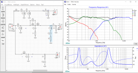
Just for giggles, I tried to design a passive crossover to mimic the performance of the active crossover. This is an academic exercise, I have no intention of building this crossover.
Drivers are the same as my active system:
SB3475NRX-6; 12 inch woofer in sealed box
SB17CAC35-4; 6 inch midwoofer
SB26CDC-C000-4; 1 inch tweeter
The impedance data I measured with DATSv3, using the right hand side drivers as installed in the cabinets.
The frequency response data was gated measurements taken from the drivers as installed in the cabinets. I spliced the near field responses to the woofer and mid below 400 Hz.
The impedance drops uncomfortably low at 300 - 400 Hz, so if I was going to build this thing, I would use the 8 Ohm version of the SB17CAC35. The crossovers at 200 and 2 k are acoustically 4th order (just like the active system), but of course they do not exactly follow the LR4 target responses. With the active system, the drivers follow the LR4 targets pretty closely.
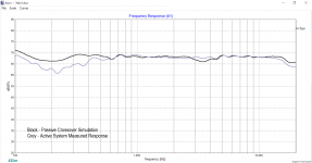
The second image is the Xsim simulation compared to the measured active system. I think it looks pretty good. The measured active response does not include a near field splice, so below 400 Hz I am showing some room effects. These effects do not show up in the Xsim simulation because those responses incorporated the near field.
It was an interesting exercise. It allowed me to again brush up on passive filter design. It confirmed to me the advantages of active DSP.
Drivers are the same as my active system:
SB3475NRX-6; 12 inch woofer in sealed box
SB17CAC35-4; 6 inch midwoofer
SB26CDC-C000-4; 1 inch tweeter
The impedance data I measured with DATSv3, using the right hand side drivers as installed in the cabinets.
The frequency response data was gated measurements taken from the drivers as installed in the cabinets. I spliced the near field responses to the woofer and mid below 400 Hz.
The impedance drops uncomfortably low at 300 - 400 Hz, so if I was going to build this thing, I would use the 8 Ohm version of the SB17CAC35. The crossovers at 200 and 2 k are acoustically 4th order (just like the active system), but of course they do not exactly follow the LR4 target responses. With the active system, the drivers follow the LR4 targets pretty closely.
The second image is the Xsim simulation compared to the measured active system. I think it looks pretty good. The measured active response does not include a near field splice, so below 400 Hz I am showing some room effects. These effects do not show up in the Xsim simulation because those responses incorporated the near field.
It was an interesting exercise. It allowed me to again brush up on passive filter design. It confirmed to me the advantages of active DSP.
Attachments
- Home
- Loudspeakers
- Multi-Way
- New active 3-Way, Hypex and SB