Sorry, we were waiting for the next (promised) instalment.
My view is that you are solving a non-problem (for audio). Fine for video, though.
My view is that you are solving a non-problem (for audio). Fine for video, though.
Some years ago I had a game to the C64 that at the starts, a voice said:
"stay here, stay quiet, stay ... forever". I don't remember the name of such game.
The next week I will publish the photos. I forgot it in my fathers' house.
"stay here, stay quiet, stay ... forever". I don't remember the name of such game.
The next week I will publish the photos. I forgot it in my fathers' house.
Dale che, que estamos impacientes, ahora sos Hitchcock ? 😀
Go ahead, we are impatient, now you're Hitchcock ? 😀
Me too 😀
Regardless of its usefulness in audio, you can't subtract the academic merit of the idea and/or audio application. 😉
Go ahead, we are impatient, now you're Hitchcock ? 😀
Sorry, we were waiting for the next (promised) instalment.
Me too 😀
My view is that you are solving a non-problem (for audio). Fine for video, though.
Regardless of its usefulness in audio, you can't subtract the academic merit of the idea and/or audio application. 😉
Wait, wait, wait, soon will post the photos. Patience is the secret!.
In video amps, the same trouble: large bandwidths, although I never see a video amplifier neutralized, as I do in FR stages.
In video amps, the same trouble: large bandwidths, although I never see a video amplifier neutralized, as I do in FR stages.

Very good I would say, Osvaldo. You have my encouragement at least.
Yes, I am also using positive fb (no, not loudspeaker current type!) and it can work quite well. Folks frown at a tube amplifier capable of a damping factor of many hundreds (as said, not load current sensing). Not that that is of any importance - but not to open another can of worms.
Only I am not fond of 12AX7s in power amplifiers, for the reason of this topic. I myself stick to lower Rp types like ECC88 (6DJ8 I believe). But just an alternative; not suggesting you start changing. I have also on occasion used inductors in series with load resistors (not as high as to be tuned, simply extending bandwidth as used in some analogue oscilloscope circuitry).
Good luck there; I will watch here. (Also, if you do not already know, watch the power stage plus transformer at h.f. With respect, some U.L. transformers are sectionalised in such a way that there could be instability tendencies round about 70 - 120 kHz. A separate subject, that.)
Very good I would say, Osvaldo. You have my encouragement at least.
Many thanks.
Yes, I am also using positive fb (no, not loudspeaker current type!) and it can work quite well. Folks frown at a tube amplifier capable of a damping factor of many hundreds (as said, not load current sensing). Not that that is of any importance - but not to open another can of worms.
Only I am not fond of 12AX7s in power amplifiers, for the reason of this topic. I myself stick to lower Rp types like ECC88 (6DJ8 I believe). But just an alternative; not suggesting you start changing. I have also on occasion used inductors in series with load resistors (not as high as to be tuned, simply extending bandwidth as used in some analogue oscilloscope circuitry).
What you did is a compensated amplifier. It was extensively used in tube B&W TV's, including early transistorized ones. This small inductors resonates with parasitic capacitances and are damped using resistors. Also oscilloscopes, as you say. I had a Paco S55 tube oscilloscope, and it used this topology, all DC coupled to 5.5MHz. Fantastic for that era.
But my idea is different. It is borrowed from RF amplifiers (Tuned) in which the parasitic capacitances in place of being tuned, they are cancelled (in fact the capacitances can't be cancelled, but their effects, yes), injecting in the grid of the tube under question, a signal of equal magnitude but opposite in phase respect to the signal going down from plate to grid via Miller Effect.
Good luck there; I will watch here. (Also, if you do not already know, watch the power stage plus transformer at h.f. With respect, some U.L. transformers are sectionalised in such a way that there could be instability tendencies round about 70 - 120 kHz. A separate subject, that.)
OK, many thanks. My circuit is still under development, and need some improvement, but my idea of neutralize the the amplifier to get the maximum bandwidth of the amp. Respect to OPT, see my post called "Hombrewed toroidal transformers" in this forum (In tubes/valves) sector. What I need is to take the photos to share the results, but my idea is working better than I expected.
Last edited:
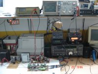
Here are the photos I promised (1 of 2)!
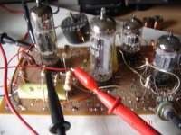
1) The workbench: at bottom, ham radio sets, and one of the 486's. nearer, the DUT.
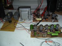
2) The test setup: DUT, power supply and voltage regulator.
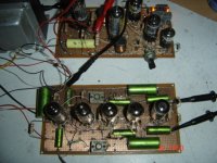
3) The DUT (Device Under Test) near board with 5 tubes aligned,
4) The DUT (Note the 2 mica compression trimmers).
5) The oscillogram with the trimmers out.
6) The amplifier just trimmered (Neutralized).
7) The amplifier overcompensated.
1) The workbench: at bottom, ham radio sets, and one of the 486's. nearer, the DUT.
2) The test setup: DUT, power supply and voltage regulator.
3) The DUT (Device Under Test) near board with 5 tubes aligned,
4) The DUT (Note the 2 mica compression trimmers).
5) The oscillogram with the trimmers out.
6) The amplifier just trimmered (Neutralized).
7) The amplifier overcompensated.
Attachments
Last edited:
Here are the photos I promised (2 of 2)!
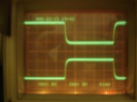
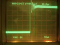
Only one channel viewed, 50VPP (limiting output voltage is 80V, so no grid current, no plate saturation, only amplification) 1 KHz (The test output from oscilo to calibrate probes.).
1) The amplifier undercompensated. Note the cursors approaching the slew time.
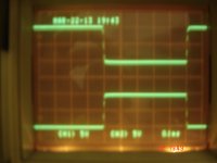
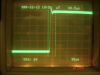
2) The amplifier just compensated.
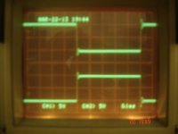
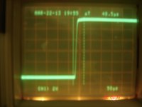
3) A bit of overcompensation (Note peaking).
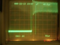
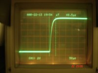
4) More overcompensation (Peaking and ringing).
5) Still more overcompensation (The amp breaks into oscillation).
Comments? Suggestions?.
Only one channel viewed, 50VPP (limiting output voltage is 80V, so no grid current, no plate saturation, only amplification) 1 KHz (The test output from oscilo to calibrate probes.).
1) The amplifier undercompensated. Note the cursors approaching the slew time.
2) The amplifier just compensated.
3) A bit of overcompensation (Note peaking).
4) More overcompensation (Peaking and ringing).
5) Still more overcompensation (The amp breaks into oscillation).
Comments? Suggestions?.
Attachments
Imagination
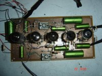
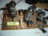
Can any of you imagine what does the regulator board do? Observe two 22mH chokes in it. Tubes (Valves) are: ECL82, EY82, ECF801, ECC82, EC900.
I have some oscillograms of it.
Popilin, SHUT UP! please.
You must need lots of imagination, this circuitry is unique in the world in its class.
Can any of you imagine what does the regulator board do? Observe two 22mH chokes in it. Tubes (Valves) are: ECL82, EY82, ECF801, ECC82, EC900.
I have some oscillograms of it.
Popilin, SHUT UP! please.
You must need lots of imagination, this circuitry is unique in the world in its class.
Attachments
Last edited:


Beautiful, you did it ! Congratulations !
Another tool for the box, thanks !

Thank you. Since now, buy lots of 3-30pF trimmers for your future amplifiers and or designs.
Only one channel viewed, 50VPP (limiting output voltage is 80V, so no grid current, no plate saturation, only amplification) 1 KHz (The test output from oscilo to calibrate probes.).
1) The amplifier undercompensated. Note the cursors approaching the slew time.
2) The amplifier just compensated.
3) A bit of overcompensation (Note peaking).
4) More overcompensation (Peaking and ringing).
5) Still more overcompensation (The amp breaks into oscillation).
Comments? Suggestions?.
Interesting work.
In the second trace ("Just Compensated"), the top of the trace appears thicker than with no compensation. Might there be some high frequency noise introduced by the compensation process?
Yes, a local 990KHz AM carrier. Some tents of kilowatts at 20Km more or less.Interesting work.
In the second trace ("Just Compensated"), the top of the trace appears thicker than with no compensation. Might there be some high frequency noise introduced by the compensation process?
Also the camera's focus at such short distances, 10 cm (4") isn´t too good.
Last edited:
I forgot to write that the amplifier is capable of catching and amplify the AM carrier without detecting it, which is the key point in my scheme.
 Edited thread title per Osvaldo's request to more accurately reflect the current direction of the discussion. 😀
Thank you, Kevin. I expect the thread be of your interest too.
I forgot to mention that the Marantz 9 also used the cross-coupled cap trick. So this has a long and honorable history.
And the Marantz 8B IIRC.
Well, OK, as I supposed this thread appears to be useless.
Please any mod may erase all it?
Many thanks.
Please any mod may erase all it?
Many thanks.
- Status
- Not open for further replies.
- Home
- Amplifiers
- Tubes / Valves
- Neutralizing An Amplifier